
Home / Documentation / Control console manual
Download the original PDF (1529 kB)
This page reproduces the text of the PDF above without alteration, so the document can be read, searched and linked to directly.
- Type
- BASEBALL_3
- Options
- 0000
- Version
- CXvF / CX_402_v1.HEX
The above information should match the label on the bottom of your control console.
The purpose of this handbook is to explain how to use and maintain the Electro-Mech MM-Style scoreboard control console for baseball or softball. The explanations and examples are based on the CX-Series console driver hardware loaded with software version 4.0.2. Earlier versions of our hardware and software behave similarly, but not identically in all situations.
Model LX1064 is the primary scoreboard model supported by this combination of hardware and software. In addition, the console can operate model LX1244 along with several baseball scoreboards without the clock feature. These include LX1020, LX1030, LX1050, LX1060, LX1070, LX1250, and LX1260.
Seven Ways to Stay Safe and Make Your Console Last Longer
1 - Don't remove the grounding pin from the power cord. It's there to help keep you from getting shocked. If your receptacle only handles two-pronged power cords then your wiring was probably installed sometime before President Hoover left office. It's time to upgrade.
2 - Keep your console dry. We've designed our consoles with outdoor activities in mind, but find some shelter if it is raining. The box is not waterproof. Drinks spilled over the keypad can lead to trouble too.
3 - Unplug both the power and data cables when you are not using the console. Noise over these cables -- either from lightning, glitches in the power line, or some other accident -- can damage the console. Leaving the console connected 24-7 just increases your risk of getting it fried.
4 - Store the console in a clean, dry, secure area. Leave it where somebody can kick it, drop it, pile stuff on top of it, or steal it, and you can expect your console will get kicked, dropped, piled on, and stolen. See also the "keep your console dry" tip above. Neither sprinkler systems nor natural sources of precipitation are beneficial to your control console.
5 - If you must open the console box, unplug the power and data cables. Yes, it is possible to get shocked if you go poking around inside the console.
6 - Don't plug something into the console that doesn't belong there. The stereo connector (some configurations have more than one) in the back plate of the console is the same kind used by audio equipment. The RJ-45 connector (some configurations lack this) for the hand-held clock switch is the same type you often see in wired computer networks. Accidently plugging an audio amplifier or Ethernet access point into your scoreboard control console can cause problems -- both to your console and to your audio and networking equipment. A common mistake we see our customers make is to accidentally plug public address equipment into the junction box that leads to the scoreboard. This often fries components in the scoreboard.
7 - Check out your equipment before game day. We're always happy to answer questions, walk you through solutions, repair damage, or send replacement parts. But if your game starts in ten minutes, there is often not much we can do to help you. Make sure your scoreboard is in good working order a few days before the game so that, however unlikely the chance of a problem, there will be time to solve it.
Console Parts and Accessories
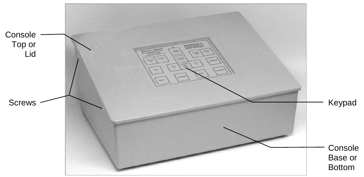
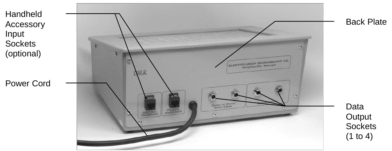
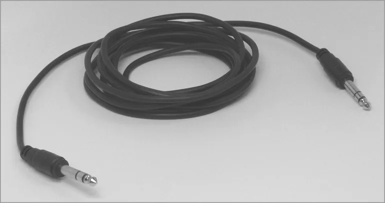
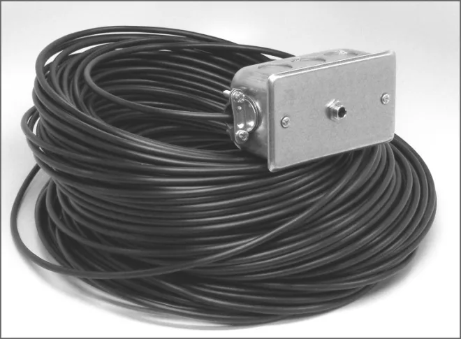
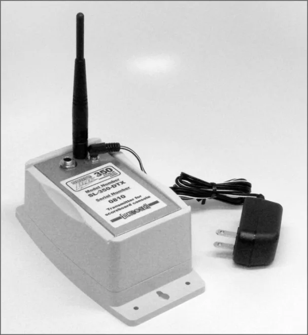
This is a generic set of photos identifying parts of the console and accessories. You should receive a packing slip or other paperwork with your order that tells specifically what parts you are supposed to have. Your configuration may be different.
Hooking Up and Powering Up the Console
1 - Apply power to the scoreboard.
2 - Place the console on a sturdy desk or table so that you have a clear view of the game's action, the scoreboard, and the console's keypad. You may hold the console in your lap, if you find it comfortable that way.
3 - Attach any wired hand-held devices. If your system includes a start/stop switch for your Clock or some other hand-held device, plug the accessory into the RJ-45 jack on the back of the control console. Some configurations do not include this jack. Some have a single jack. Some have two. If you have two RJ-45 jacks, they will be wired the same way, so it doesn't matter which device is plugged into which jack (despite what the labeling on some older consoles indicates).
4 - Attach one end of the stereo data patch cable to the data output connector on the back plate of the console. In some configurations, there may be more than one stereo socket on the back of the control console. They all provide an identical signal, so it doesn't matter which one you choose.
5 - Attach the other end of the stereo data patch cable to the junction box. If you have the ScoreLink wireless RF system, refer to the ScoreLink owner's handbook for details.
6 - Plug in the console power cable to a standard electrical outlet.
About one out of every few hundred customers asks us the question, "How do you turn the console on and off?" There is no power button on the console. If it's plugged in, it's on. The logic here is that, for most installations, the scoreboard is not used very often. During the down time, the console needs to be disconnected from the scoreboard and from power to prevent damage from line noise and power surges. A power switch would discourage that good habit and provide a false sense of security.
Likewise, the scoreboard should be disconnected from power when not in use. For this reason, the console has no means of turning the scoreboard on or off. However, a freshly powered-up scoreboard will display no information until it receives a good signal from the control console. So in order to "turn on" the scoreboard display, you have to power up and connect the control console.
Control Console Initialization
The first time you use your control console, it will display the following information on the scoreboard (some scoreboard models do not displays all the functions listed):
- Left (Guest) Score
- 0
- Right (Home) Score
- 0
- Inning
- blank
- Ball Count
- blank
- Strike Count
- blank
- Out Count
- blank
- Hit Indicator
- blank
- Error Indicator
- blank
- Game Clock
- 12:00 (Minutes:Seconds)
- Clock Activity Indicator
- blank
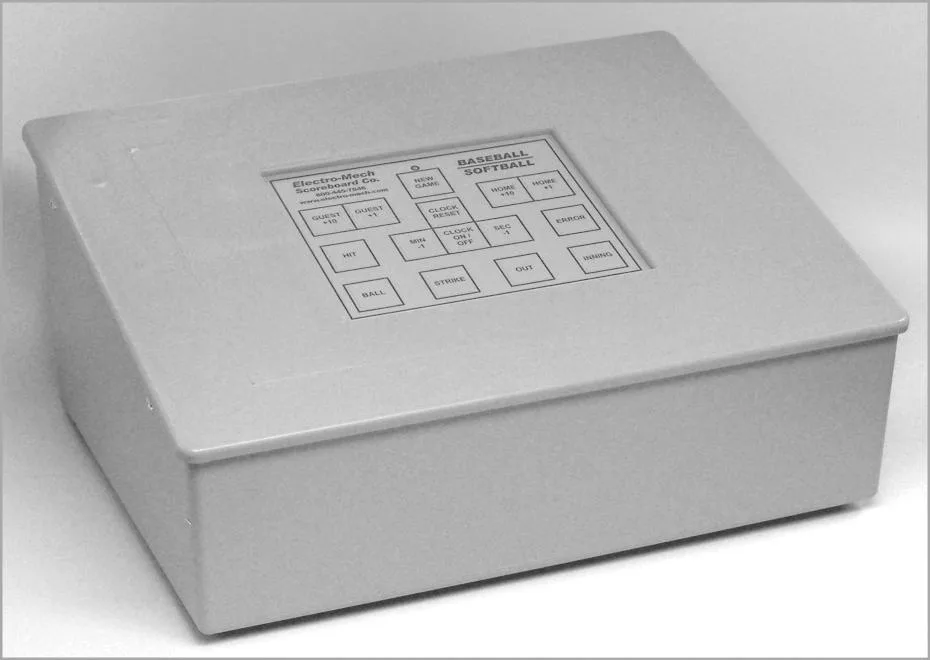
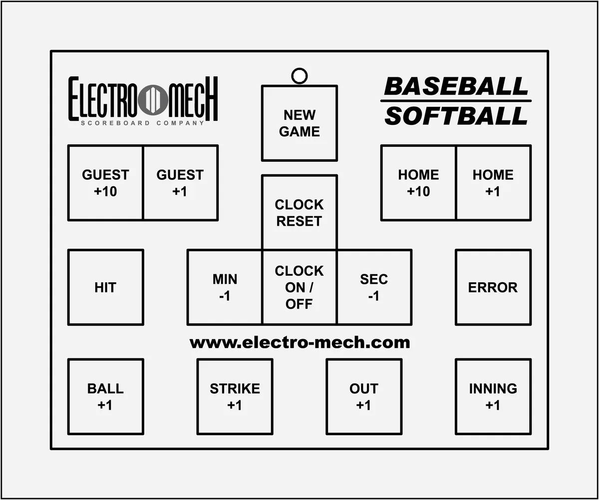
Keypad Layout
Key-By-Key Operation
This section will provide a key-by-key explanation of the console features. At the top center of the keypad there is a red LED indicator. This LED should be illuminated whenever the control console is connected to power.
[GUEST +10] - Add ten Runs to the Guest Score.
[GUEST +1] - Add one Run to the Guest Score.
[HOME +10] - Add ten Runs to the Home Score.
[HOME +1] - Add one Run to the Home Score.
[HIT] - Flash the Hit Indicator.
[ERROR] - Flash the Error Indicator.
[BALL +1] - Add one to the Ball Count. Adding one to a Ball Count of 3 blanks the Ball Count display.
[STRIKE +1] - Add one to the Strike Count. Adding one to a Strike Count of 2 blanks the Strike Count display.
[OUT +1] - Add one to the Out Count. Adding one to an Out Count of 2 blanks the Out Count display.
[INNING +1] - Advance to the next Inning. The console tracks 19 Innings, although many scoreboards lack the extra "half digit" to display Innings above 9. For these scoreboard models, Innings 10 through 19 will display as 0 through 9. Adding one to the 19th Inning wraps the counter around to 0, which is displayed as a blank on the scoreboard.
[CLOCK ON / OFF] - Start and stop the Game Clock. This button can cause some confusion if you happen to have a scoreboard WITHOUT a Game Clock display. If you press the button by accident, the console will begin running its Clock counter internally. As long as the Clock is running, whether you can see it or not, the console assumes a game is in progress. For this reason, you cannot use the [NEW GAME], [CLOCK RESET], [MIN -1], or [SEC -1] buttons while the Game Clock is running. If you have a scoreboard without a Game Clock and find that your [NEW GAME] button seems to be broken, try pressing [CLOCK ON / OFF] to stop the Game Clock inside the console.
[MIN -1] - Subtract one Minute from the Game Clock. This button is disabled while the Game Clock is running. It is ignored if the Game Clock has reached 0.
[SEC -1] - Subtract one Second from the Game Clock. This button is disabled while the Game Clock is running. It is ignored if the Game Clock has reached 0.
[CLOCK RESET] - Cycle the Game Clock through initial values: 15:00, 30:00, 60:00, 90:00, and then back to 15:00. Each time you press the [CLOCK RESET] button, the console selects the next highest reset value. So, if your Game Clock is showing 12 minutes (or any other value less than 15 minutes), pressing [CLOCK RESET] sets the time to 15 minutes. Pressing it again would take you to 30, etc. This button is disabled while the Game Clock is running.
[NEW GAME] - Does nothing when pressed alone. Press [NEW GAME] and, within two seconds, press [CLOCK RESET] to initialize the control console to its default values. The scoreboard will display Scores of 0, blank Innings, etc. Press [NEW GAME] and, within two seconds, press [NEW GAME] again to test the LEDs on your scoreboard. The console will send data that lights all scoreboard features. To exit this Test Mode, press [NEW GAME] again. This button is disabled while the Game Clock is running.
Wired Handheld Clock Start / Stop Switch
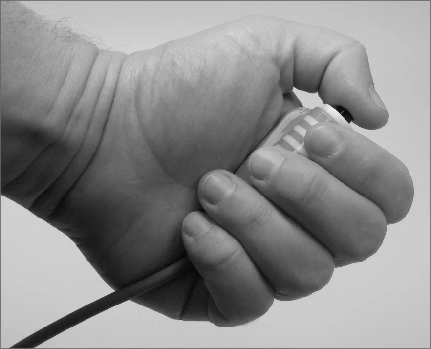
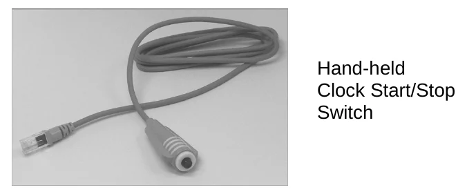
Some of our scoreboards with Game Clocks include the option for a pendant-style switch that plugs into the back of the control console and allows a separate operator the ability to start and stop the Clock. The RJ-45 style connector at one end of the handheld unit's cable can plug into either the console sockets labeled "H1" or "H2" in the "SWITCH INPUTS" area. On older control consoles, these sockets are labeled "CLOCK Hand-held" and "DGT / SC Hand-held". The pendant end fits nicely in your hand so that your thumb rests on the switch. Press the switch once to start the Clock. Press the switch again to stop the Clock.
This option is not available for most baseball control consoles.
Control Console Power Down and Storage
There is no "OFF" switch on the control console; nor is there a function on the console that turns the scoreboard off. The scoreboard should be disconnected from power when not in use. Electro-Mech recommends installing a disconnect switch for all permanently mounted scoreboards. You may simply unplug a portable scoreboard model and store it between games.
You should unplug your control console both from its power receptacle and from its data cable when you are not using it. Electro-Mech offers a carrying case that provides a convenient way to store and transport the console along with various cables and other accessories. Whether or not you have a case, you should store the console in a safe, dry location between games.
If the console loses its connection with the scoreboard while the scoreboard is powered, the scoreboard will freeze up -- showing the last known Inning, Scores, and other information it received from the console. The scoreboard will synchronize with the console again as soon as you reestablish the connection.
If the scoreboard loses power with the console still connected and powered, nothing will happen other than the scoreboard display going blank. Again, the scoreboard will synchronize with the console as soon as it receives power.
If the console loses power -- either because you intentionally unplug it or because of something unexpected -- it will save the current game information to its internal memory. When you next apply power to the console, the game data will restore automatically after a few seconds.
Jumper Settings
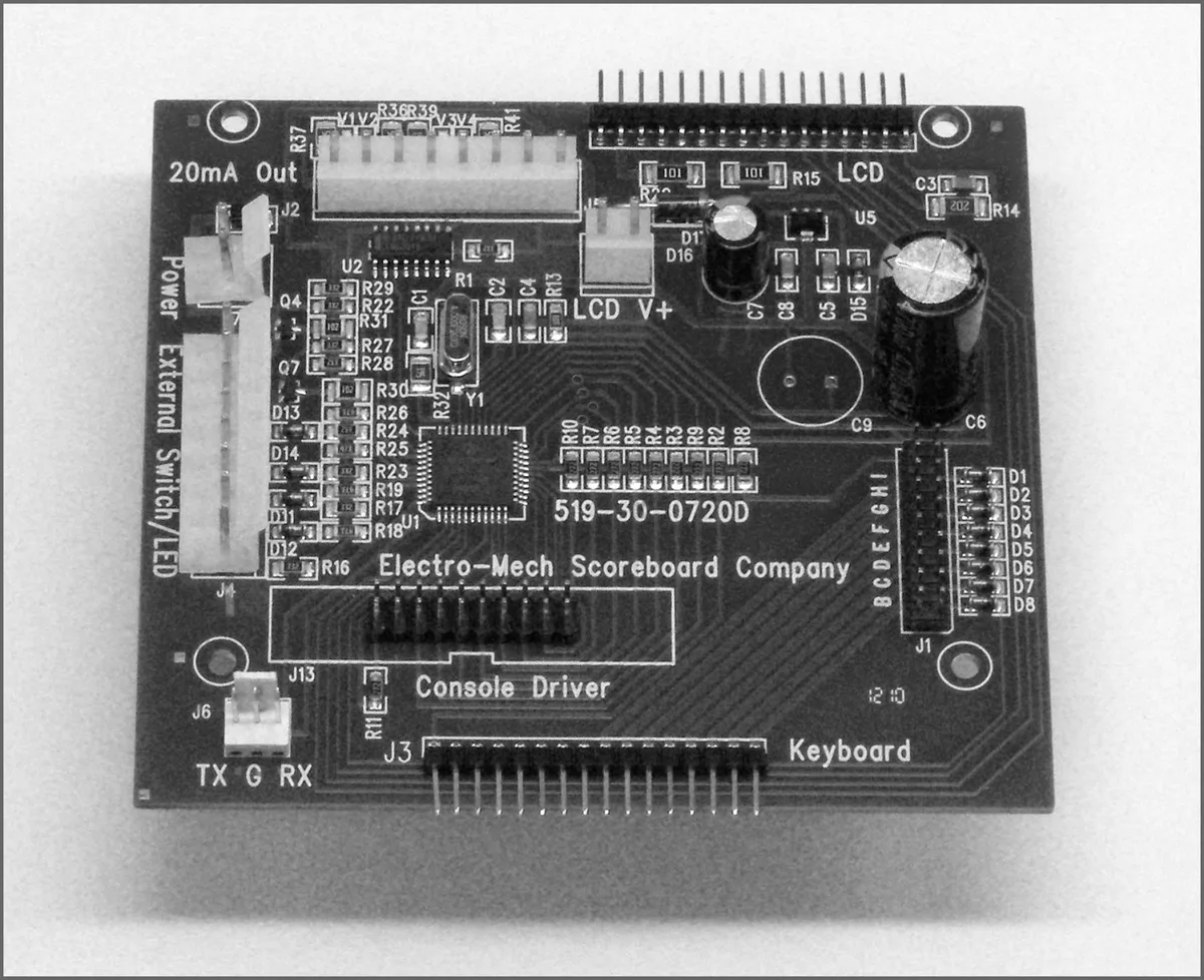
*** Important: If you plan to open up the console and do work inside the box, make sure the power cable is disconnected from the receptacle! ***
The PCB that is the heart of the CX console is called the CX driver. This driver contains a set of jumper pins that can be used to tell the software how to behave. By installing shunts across a pair of pins, you are, in essence, closing a switch that tells the program to do something. On some CX drivers these pins are labeled B through I, A through I, or A through J. On other drivers the A, B, C,... labels are missing, but you will find a corresponding diode next to pins B through I (A and J are not for jumpers). The diodes are labeled D8 through D1 (D8 = B, D7 = C, etc.).
Jumper pins A and J are used for attaching a programming cable to the CX driver and don't really do anything in this context. Pins F, G, H, and I are the "Board Type Jumpers" that determine the sport. So, for instance, by adding a shunt across the H pins, you can make your console think it is operating an Electro-Mech football scoreboard rather than a baseball scoreboard. This table summarizes the jumper settings for the Board Type Jumpers:
| Board Type | F | G | H | I | Models / Comments |
|---|---|---|---|---|---|
| BASEBALL_3 | LX10xx, LX12xx, LX134x | ||||
| BASEBALL_4 | X | LX1360 | |||
| FOOTBALL_4 | X | LX1360, LX31xx | |||
| BASEBALL_1 | X | X | LX10xx, 11xx, 12xx, 134x | ||
| BASEBALL_2 | X | Not used | |||
| SOCCER_LX | X | X | Not a part of CX_402 Software | ||
| SOCCER | X | X | Not a part of CX_402 Software | ||
| HOCKEY | X | X | X | Not a part of CX_402 Software | |
| LINESCORE4 | X | Not used | |||
| LINESCORE5 | X | X | LX16xx, LX17xx | ||
| FOOTBALL_1 | X | X | LX3xxx (except LX31xx), LX7520, LX7640 | ||
| BASKETBALL | X | X | X | LX2xxx (except Player Stats), LX72xx | |
| MP-14X | X | X | Not used | ||
| MP-15X | X | X | X | Not used | |
| MULTISPORT | X | X | X | LX1320, LX137x, LX1390, LX3450, LX6324 | |
| HOCKEY_LX | X | X | X | X | Not a part of CX_402 Software |
Pins B, C, D, and E are the "Option Jumpers". Each one typically controls one of four options for a given Board Type. This document discusses the options for the BASEBALL_3 Board Type only. You'll have to look at the Owner's Handbooks for consoles configured for the other Board Types if you are curious about their Option Jumpers.
Jumper B = Scores to 19 (Install this jumper to have Scores to 19 instead of 99) Jumper C = Minutes Clock (Add this to indicate 2-Digit Clock with Minutes only) Jumper D = Hours Clock (Add this to indicate a Clock with an Hours digit) Jumper E = B-S-O to 4-3-3 (Install this jumper for Balls to 4, Strikes & Outs to 3)
Adding Jumper C (without Jumper D in place) indicates a 2-Digit Game Clock that counts down Minutes, which available with Model LX1062 and Model LX1340.
Adding Jumper D (without Jumper C in place) indicates a 3-Digit H:MM Game Clock, which is available with Model LX1241 and Model LX1341.