
Home / Documentation / Owner's manual
Download the original PDF (4074 kB)
This page reproduces the text of the PDF above without alteration, so the document can be read, searched and linked to directly.
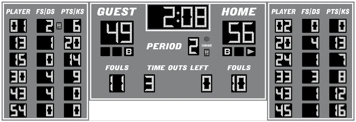
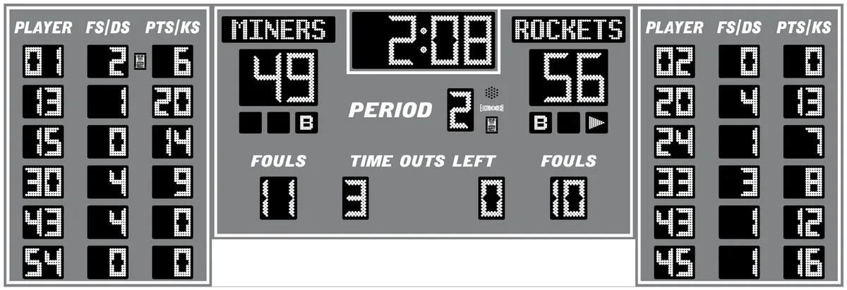
The purpose of this manual is to explain how to install and maintain the Electro-Mech Model LX2556 Indoor Multi-Sport scoreboard as well as the LX2556-ETN version of this product, which features Electronic Team Names. Operation of the scoreboard is covered in the manuals that ship with the control consoles.
BEST PRACTICES FOR PERSONAL SAFETY AND PRODUCT CARE
Thank you for choosing Electro-Mech products for your athletic facility. We hope you will be pleased with the performance and appearance of your scoreboard. The information in this document will help you maintain the equipment in its best condition.
Receiving Your Scoreboard
Depending on the shipping method, the scoreboard may be protected by cardboard sheets, a partially open wooden crate, or a complete enclosure. It is important to inspect the scoreboard packaging for damage when it arrives -- before signing any paperwork telling the trucking company you have received everything in good condition. If you see damage to the packaging, it is possible the scoreboard has been damaged too. Where you find dents, scrapes, or holes in the packaging, peel back the cardboard or other packing materials to expose the scoreboard cabinet. Make notes on the paperwork provided by the trucking company before accepting delivery. If the damage appears to be severe, refuse the shipment. Always contact us as soon as possible if you suspect shipping damage.
For larger scoreboards (and any separate ID panels that may have shipped with them), we supply eye bolts in the top of the cabinet for lifting. These eye bolts usually remain exposed while the scoreboard is in its shipping package. You may lift the packaged cabinet by the eye bolts to remove it from the truck and move it around prior to installation. You may also transport the cabinet on dollies. If the scoreboard is more than twelve feet wide, we recommend using a dolly at least every 10 feet along the bottom of the cabinet to provide support and prevent sagging.
We recommend keeping the scoreboard in its packing materials until the day of installation. It is important to keep the packing materials dry while they are on the scoreboard. Wet cardboard can adhere to the surfaces and damage the finish.
If your scoreboard shipped in a wooden crate, the pieces are nailed together. Pry the crate apart, taking care to avoid scraping the scoreboard with tools, nails, or lumber. Make certain to pry the wooden pieces apart from each other rather than trying to apply force against the scoreboard cabinet. Aluminum is strong, but a steel crowbar is stronger.
Once the crate is out of the way, remove the cardboard padding. You may need to remove a few labels adhered to the side of the cabinet for shipping. At this point, your scoreboard is unpacked and ready to be installed.
Storage Prior to Installation
Unless you are planning to install your scoreboard the same day it arrives, you will need to prepare a clean, dry, secure area for storage. Even though your scoreboard is
designed ruggedly, you will need to keep it away from moisture, dirt, accidental damage, and abuse.
Stand the scoreboard cabinet upright; never lay it face down or face up. Never stack things on top of the scoreboard cabinet while it is in storage.
These recommendations apply to ID panels and other items that may have shipped with your scoreboard.
Conditions of Installation and Use for Indoor Scoreboards
This scoreboard is designed for installation and use in a dry environment. Do not attempt to install or operate this scoreboard outdoors or in a wet location.
Indoor scoreboards are typically attached to a wall. The cabinet includes a set of mounting tabs so that the display may hang from bolts anchored to the wall. Optionally, you may wish to suspend the scoreboard from the ceiling using the eye-bolts provided in the top of the cabinet. Whatever the mounting method, it is important to make sure the hardware, as well as the structure on which the scoreboard is to be mounted, can support the weight of the display and any ID panels or other accessories.
The scoreboard receives power from a standard 120 VAC electrical outlet. When it is not in use, you should disconnect it from power. For this reason, we recommend installing a dedicated disconnect switch on within sight of the scoreboard. In the "off" position, the switch should isolate all load carrying conductors (not the ground). This will help protect the scoreboard electronics from nearby lightning strikes and other power fluctuations that might otherwise travel along the power cables.
PRODUCT SPECIFICATIONS
General Description:
- Model LX2556 is an electronic scoreboard designed for permanent installation indoors and intended primarily to display time and scoring information for basketball or volleyball.
Standard Package Includes:
- One scoreboard cabinet
- Two control consoles
- Two stereo patch cables
- Two junction boxes
- Two stereo plugs
Scoreboard Cabinet Dimensions and Weight:
- 17 ft 10 in (W) x 6 ft (H) x 6 in (D), 290 lb
Scoreboard Cabinet Constructions and Finish:
- The cabinet includes a self-supporting frame constructed from extruded aluminum channel and formed aluminum pieces. The face and back sections are made from aluminum sheet material. The masks protecting the LED displays are also made from aluminum sheet material. Mask and face pieces are finished with enamel paint. All other cabinet surfaces are mill finish. Captions, optional accent striping, and other decorative elements are cut from interior grade vinyl. Electro-Mech offers eighteen standard paint and vinyl colors. Other color options are available as an upgrade.
Overview of LED Displays:
- Red, amber, or green LEDs (light emitting diodes) mounted on printed circuit boards form all digits, indicators, and text displays. The circuit boards are mounted behind aluminum masks, painted black to increase contrast. The masks are designed to allow the epoxy shells of the LEDs to protrude past the scoreboard face, maximizing viewing angle while providing impact absorbing protection from contact with stray balls and other flying objects. The LEDs may be dimmed to reduce glare under changing lighting conditions. They are rated for 100,000 hours of use.
Display Features:
- 4-Digit Game Clock, Red, 12 inches tall, shows Time in MM:SS up to 99:59, counts up or down, can show Tenths of Seconds during the final minute of a down-counting Period, can show HH:MM in Time of Day Mode, can show a Segment Clock in Practice Segment Timer Mode
- 2.1-Digit Scores (one set for Guest, one set for Home), Amber, 12 inches tall, to 199
- 1-Digit Period, Green, 9 inches tall, to 4
- 1.1-Digit Team Fouls (one set for Guest, one set for Home), Amber, 9 inches tall, to 19
- 1-Digit Time Outs Left (one for Guest, one for Home), Red, 9 inches, to 9
- "B" Indicators for Bonus/Double Bonus (one set for Guest, one set for Home), Green, 3 inches tall
- Arrow Indicators for Next Possession (one for Guest, one for Home), Red, 3 inches tall
- 12 each 2-Digit Player Number (six sets for Guest, six sets for Home), Red, 6 inches tall, to 99
- 12 each 2-Digit Player Fouls/Digs (six sets for Guest, six sets for Home), Green, 6 inches tall, to 99
- 12 each 2-Digit Player Points/Kills (six sets for Guest, six sets for Home), Amber, 6 inches tall, to 99
- Optional Electronic Team Names (one ETN display for Guest, one ETN display for Home), Amber, 9x48 pixels, 5-inch x 27-inch active display area, capable of showing up to 9 characters
Additional Standard Scoreboard Features:
- All serviceable components accessible from the front of the cabinet
- Internally mounted Horn
- Built-in AC power cable, 6 feet long
- Data output ports for daisy-chaining additional displays
- Output receptacle to power Visual Horn Indicators
- Eye bolts for lifting
- Integrated mounting tabs
Control Consoles:
- Two control consoles are included -- one for the main scoreboard, one for the player statistics panels.
- Each console features custom software running on an internal microprocessor, a 32-character LCD display, a 37-button sealed membrane keypad, and a 6-ft. power cord. The console enclosure consists of an ABS plastic base and top with a metal back plate.
- Each console includes four data output ports. Each port can directly drive a scoreboard display (or stat panel set) through a single cable run and indirectly drive up to ten displays in perfect synchronization via daisy chaining. The number of synchronized displays is practically limitless when using the optional ScoreLink RF communications system.
- The software includes support for, Electronic Team Names, Practice Segment Timer Mode, Time of Day Clock Mode, 50 levels of brightness, and other features.
Optional Equipment and Features:
- Data cable for hard-wired installations (two runs required)
- ScoreLink RF communications system for wireless data transmission (two sets required)
- Hard carrying cases for control consoles and accessories
- Wired or wireless hand-held controllers to start and stop the Game Clock
- Non-illuminated, illuminated, and fully electronic ID panels, message centers, and video displays
- Stadium Sound systems
- Backboard-mounted LED light bar kits to serve as visual Horn indicators
Power Requirements:
- Without ETNs, LX2556 requires one circuit providing 5.6 amps, 120 VAC, 60 Hz.
- LX2556-ETN requires one circuit providing 6.2 amps, 120 VAC, 60 Hz.
- Power enters the scoreboard cabinet via an attached 6-foot long cord designed to plug into a standard (NEMA 5-15R) power receptacle.
- Each control console requires one circuit providing 0.5 amps, 120 VAC, 60 Hz via standard (NEMA 5-15R) power receptacles.
- Electro-Mech recommends installing a dedicated breaker to control power to the scoreboard.
- All power receptacles must be properly grounded.
Mounting Requirements:
- The standard configuration of this scoreboard is designed to be mounted indoors on a wall or suspended from the ceiling.
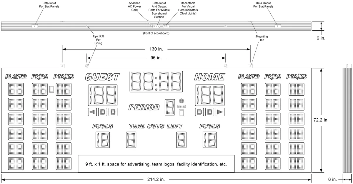
- To use the standard mounting tabs for installation on a wall, the installer must securely attach two lag bolts, or similar hardware, with a maximum diameter of 3/8 inches. Bolt spacing should be 130 inches center-to-center.
- The scoreboard cabinet may be suspended from the two eyebolts attached along the top of the frame. These eyebolts are spaced 96 inches center-to-center and have a 1-inch diameter opening to accept chain or cable.
Warranty Information:
- The standard limited warranty covers factory labor on parts returned to Electro- Mech within five years of the scoreboard's date of invoice.
- The complete standard warranty statement is included near the end of this document.
- Additional support plans are available.
PLANNING YOUR SCOREBOARD INSTALLATION
A good plan is important to the success of any project, and installing a scoreboard is no exception. An important first step in planning for your scoreboard is determining where to put it. The key factors here are visibility and accessibility.
By "accessibility" we mean the ease with which you can get people, equipment, cabling, etc. to the scoreboard during installation and the ease of access for service in the future. If you position the scoreboard so that using a lift or ladder to reach it is impractical, you will almost certainly add cost to the installation and to service calls.
By "visibility" we mean the ease with which spectators, participants, and the operator of the scoreboard can see the display. Because every sports facility is unique, there is no one-size-fits-all way to describe the perfect scoreboard location. We can tell you that the vertical placement of the scoreboard should be high enough to give spectators a clear line of sight over the heads of players but low enough allow to fans to glance up from the game and check the score without straining their necks. For safety, you will want to keep the bottom of the cabinet at least eight feet above the floor (to prevent people from smacking their heads against it).
Unless you've selected a very small scoreboard for a very large facility, viewing distance is not usually an issue. The rule of thumb in the sign industry is that, for lighted characters, every inch of height provides 50 feet of viewing distance. For comfort, and because you also need to read the captions on a scoreboard, we prefer to recommend 25 feet of viewing distance per inch of digit height. Model LX2556 uses 12-, 9-, and 6- inch tall digits, meaning it can easily be seen from 150 feet. If your players and spectators need to be several hundred feet or more from the scoreboard, your facility may require a larger display.
For some indoor facilities, it is important to make sure people cannot -- accidentally or intentionally -- interfere with the scoreboards or cables connected to it. For example, indoor scoreboards are sometimes mounted along the front facade of balcony seating. This can make it tempting for fans to reach over the balcony and touch the scoreboard, snag a cable, drop a soda on it, or otherwise make a nuisance of themselves. One solution would be to install a shield above any scoreboard in this position.
If you are planning for the construction or renovation of a new facility, then you will likely have more options for locating your scoreboard. In addition, you may be able choose helpful positions for electrical outlets, plan for conduits, and control other details that will make installation, operation, and service easier. Your scoreboard sales rep should be able to answer questions and offer advice that will help you with these plans.
If you are adding this scoreboard to an existing facility, your options may be more limited. In some cases, we can modify the scoreboard to meet special needs. An example of this would be accommodating power entry through the back of the cabinet rather than via the standard power cable on top. These sorts of details must be worked
out prior to the release of a scoreboard order. Your sales rep can guide you through the process.
The sections that follow in this document primarily discuss the details of the mechanical and electrical installation of a single scoreboard. If your project includes multiple scoreboards or other electronic displays, please check with your scoreboard sales rep to make sure you have any project level documentation you may need.
Before You Spend Your Time and Money...
Please keep in mind that the dimensions and other details referenced throughout this document are specific to the standard configuration of this scoreboard model. Before purchasing materials, running cabling, etc. you should verify with the factory that you have the right documentation for your particular project.
It is possible that a government agency, such as your local city council, will require a building permit or other documentation and approval forms related to the installation and operation of your scoreboard. In some cases the installation plan may require a stamp from a locally licensed Professional Engineer (P.E.).
ELECTRICAL INSTALLATION
This section of the manual provides information that is important for locating power receptacles, running cable, planning for conduit, and other steps needed in preparation for bringing power and data to the scoreboard. The final hookups for power and data will happen after the mechanical installation. But it is wise to plan for key pieces of the electrical installation prior to physically mounting the scoreboard.
If your scoreboard package includes special accessories such as electronic message centers or video displays, there may be additional cabling and conduit needed to support this equipment. Please consult the documentation provided with these items.
The standard configuration of this scoreboard includes a power cable attached to the top of the cabinet. Input and output ports for data are located here as well. At the factory, it is possible to relocate these connection points to accommodate special needs. Let your scoreboard sales rep know about any custom requirements BEFORE we begin building your cabinet.
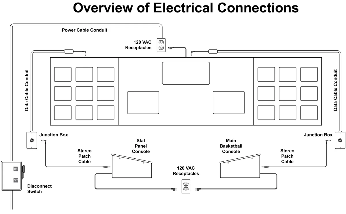
Additional Materials and Tools
The illustration on the previous page shows where power is needed and how data
cables can be routed. Data cable is not included as a standard part of the scoreboard
package, although Electro-Mech typically is the source it. Alternatively, Electro-Mech
can provide a ScoreLink wireless communication system to replace the data cable.
Other materials shown (or implied) in the illustration that are not included in the
standard scoreboard package:
- Power receptacles (at the scoreboard and at the point of operation)
- A disconnect switch (to turn the scoreboard on and off)
- Cable and conduit to supply power to the receptacles
- Conduit for the data cable (if data cable is used)
- Wire splicing kits for use with 22 AWG wire (if data cable is used)
This document assumes the installer has access to tools and skills for...
- Working with conduit and fittings
- Routing cables
- Crimping terminals, splicing, soldering, and other basic wire management
- Minor carpentry work
- Common tools such as Phillips and flat head screwdrivers, a knife, etc.
Electro-Mech recommends you find a reputable sign installer or electrician with the tools and experience to handle the type of work mentioned above. If you are unfamiliar with sign installers in your area, contact your scoreboard sales rep for recommendations.
Power Receptacles and Disconnect Switch
The scoreboard is designed to be plugged into a US standard (NEMA 5-15R) 120 VAC receptacle. We recommend providing a disconnect switch to kill power to this receptacle when the scoreboard is not in use. Each control console also requires a power receptacle. These need not be attached to a disconnect switch since the consoles can easily be unplugged and are typically stored between games. Control consoles used with external ScoreLink transmitters will need an extra receptacle for each transmitter's power supply.
Model LX2556 draws a maximum of 6.2 amps when the package includes Electronic Team Names. Without ETNs, the maximum current is 5.6 amps.
Junction Boxes and Data Cable
If your scoreboard package includes the ScoreLink wireless communication system, your work is done here. Skip to the next section.
Since this scoreboard uses two control consoles -- one for control of the primary game functions such as Time and Scores, one for tracking Player Stats -- there must be two separate runs of cable from the point of operation to the scoreboard. Your hard-wired scoreboard package includes two junction boxes, which you should permanently mount to provide a stable point of termination for the data cables. The idea is to connect the control consoles to these junction boxes via a pair of ten-foot patch cables. So the junction boxes will need to be mounted within ten feet of the position where your scoreboard operator will sit. In many gyms the junction boxes are concealed inside a larger floor box. They can be flush mounted on a wall, externally mounted on bleachers, or positioned anywhere else that is convenient. Choose a location that is protected so that the junction box and cables are not likely to be stepped on, tripped over, or have liquid (or anything else) spilled on them.
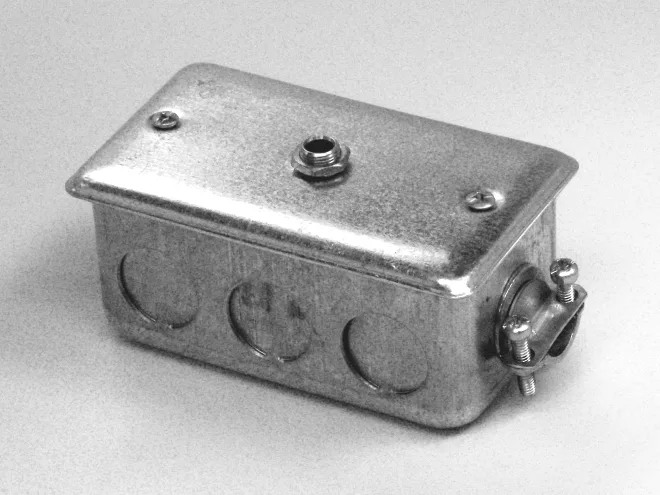
It is also important to label your junction boxes. The connectors used for scoreboard data look very much like the type used in some audio systems. Plugging audio devices into a scoreboard data line can often damage the scoreboard.
Each junction box ships with a length of cable soldered to the stereo socket and tucked inside the box. There should be no need to solder cable to this socket during the installation. Instead, splice the wires from the cable to the pigtail inside the junction box, matching colors. The wires in the pigtail are 22 AWG, and the cable should use the same size conductors. The installer must provide wire nuts, crimp splices, or other means to connect the wires.
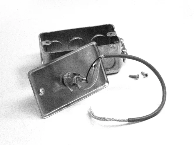
The splice point should stay inside the junction box. That is, you want to feed the long run of cable into the box rather than pulling the pigtail out. Electro-Mech provides a strain relief on one side of the junction box to secure the cable. You may choose to connect conduit directly to the junction box, in which case the strain relief will not be needed. The junction box is designed to accept 3/4-inch conduit fittings.
We recommend running data cable in conduit from the junction box to the scoreboard -- especially where the cable would otherwise be exposed. You should never run data cable in the same conduit as power cable. Having more than one run of scoreboard data cable in a single conduit is perfectly fine.
One more warning about data cable: Never split or branch the cable. The current loop signal we use to transmit data to the scoreboard will behave unpredictably if it is divided between two destinations. There are other options for getting synchronized data to two locations, including daisy chaining -- which will be discussed below. If your facility calls for a more complicated cabling plan, it is best to work out the details with your scoreboard sales rep prior to installation.
Stereo Plug
At the scoreboard end, data enters the cabinet through a port located along the top. In the case of scoreboards with stat panels, there is a separate input port for stat panel data. The illustration below is a view of the top of the scoreboard showing the standard location of the ports.

There are two common methods for bringing the last few feet of data cable to the scoreboard. One method involves installing a junction box on the wall near the scoreboard. From here you can run a patch cable to the scoreboard's data input port. The standard scoreboard package does not include extra junction boxes and patch cables for this type of cable routing. However, the materials are readily available from Electro- Mech.
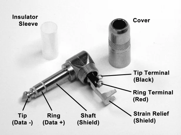
The other method uses the right-angle stereo plug assembly, which is provided with all hard- wired indoor scoreboard packages. In the case of scoreboards with stat panels, there will be two plug assemblies to terminate the two cable runs required. The assembly consists of the main plug body, an insulating sleeve, and a cover.
Connecting data cable to the stereo plug requires soldering to two terminals. Slide the cover and sleeve over the data cable before soldering. The terminal nearer the center of the plug body connects to the tip of the socket. The black wire from the data cable should be soldered to this terminal. The terminal that extends further from the center of the plug body connects to the ring of the plug. Solder the red wire here. The strain relief tabs are connected to the shaft of the plug. When you bend the tabs around the data cable, they should be in contact with the shielding or the bare drain wire.
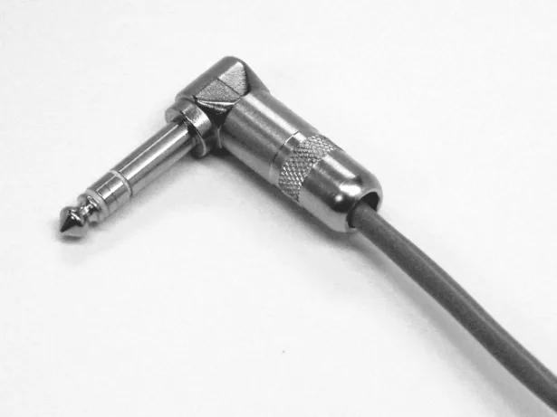
Slide the insulator sleeve over the terminals and screw the cover in place to complete the assembly. Now you will be ready to plug the data cable into the port at the top of the scoreboard when it is installed.
Managing Multiple Scoreboards
The preceding material discussed how to run data cable for a single scoreboard. When multiple scoreboards are installed in the same facility, the options can become confusing. Make sure you discuss your plans with your Electro-Mech sales rep to make certain you receive all the materials you need to meet your expectations.
The simplest (and rarest) arrangement occurs when multiple scoreboards are completely unrelated to each other. In this case, each scoreboard would have its own control console (or consoles, in the case of scoreboards with stat panels) and its own data cable.

Daisy Chaining
Another simple case is when multiple scoreboards are always run in synchronization from a single control console. There are two ways to run cable for this setup. By running a secondary data cable from the data output port of one scoreboard to the data input port of the second scoreboard, you will like the two displays permanently.
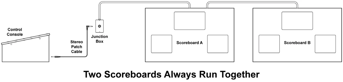
This daisy chaining technique can be extended, with a third scoreboard connected to the second, a fourth scoreboard connected to the third, on so on. We recommend daisy chaining no more than ten scoreboards from a single data source. Each scoreboard in the chain adds a few milliseconds of propagation delay. After the tenth scoreboard, this delay would be noticeable when the Clock is counting Tenths of Seconds.
The second technique for running scoreboards in synch is to use two runs of cable, each patched to a separate output of the same control console. We recommend this technique, when conditions in the gym allow it, because it offers the option of running the scoreboards separately in the future. This is discussed further in the next section.
Sometimes Separate, Sometimes Together
As mentioned previously, the current loop signal that sends data from the control consoles to the scoreboard cannot be split. That is, you can't take the signal from one data port on the back of the control console to two or more scoreboards. Instead, you should plan for a separate cable run for each scoreboard (or for each chain of scoreboards, if you plan to daisy chain). Each control console includes four output ports, so it is possible to directly drive four hard-wired scoreboards (or chains) from one console.
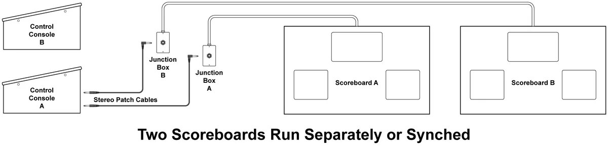
In the illustration above, two scoreboards are linked through Control Console "A" because both patch cables are plugged into data ports on the back on the console. If activities in the gym require two separate consoles, the patch cable connected to the "B" junction box can be moved to the "B" console.
In facilities with multiple scoreboards displays, including shot clocks and locker room clocks, many combinations of these techniques are possible. You may use one port on the back of your control console to drive a scoreboard and (via daisy chaining) a set of shot clocks, another port to drive a second scoreboard, and a third port to drive several daisy chained locker room clocks. As always, we recommend discussing these options with your scoreboard sales representative prior to placing your order.
MECHANICAL INSTALLATION
This section of the manual describes installing the scoreboard, in its standard configuration, on lag bolts attached to an interior wall. If your scoreboard is to be customized with additional ID panels or requires other special mounting considerations, please contact the factory to request details specific to your project. If you have unique requirements and would like to change the position or size of our mounting hardware to accommodate them, we can probably help you out. But we need to find out BEFORE we start building the cabinet. Let your scoreboard sales rep know about any special needs as early in the process as possible.
Additional Materials and Tools
Most indoor scoreboards are installed with their backs flat against a wall. The mounting tabs and eye bolts attached to the scoreboard cabinet are simple and generic enough to accommodate a variety of techniques for hanging the scoreboard on other structures. However, for the sake of clarity and brevity, we will assume a wall. We will further assume that the wall is capable of supporting the weight of the scoreboard and any accessories to be mounted with it.
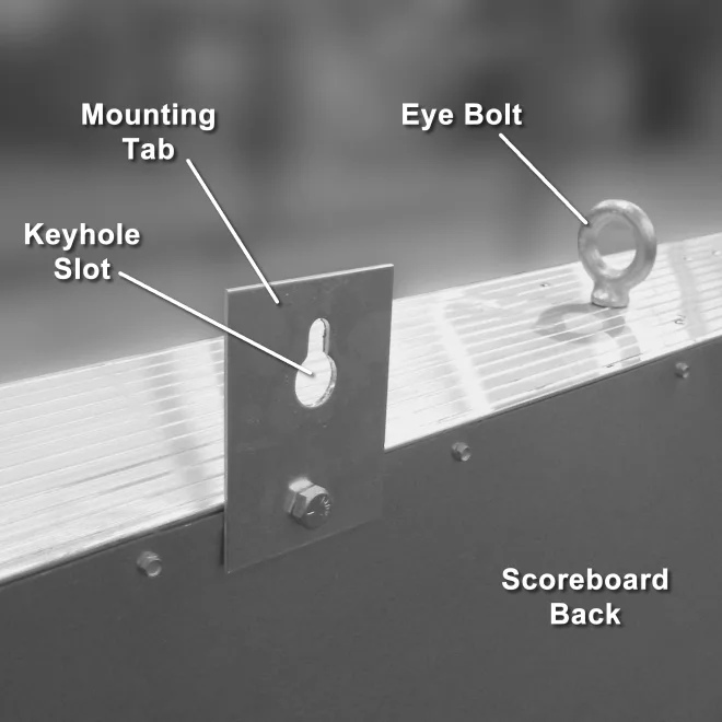
The wall could be made of cinder blocks, framed with wood and covered in drywall, or constructed any number of other ways. Because different fasteners are appropriate for different walls, we cannot specify a particular type of fastener. This document uses the term "lag bolt" to generically represent whatever fastener is best suited for the type of structure on which the scoreboard will hang. To use the mounting tabs provided with the scoreboard, you will need two such lag bolts. The keyhole slots stamped into the mounting tabs allow for a bolt diameter of 3/8 inches or less.
In addition to the wall and the two lag bolts, this document also assumes the installer
has access to tools and skills for...
- Working at the height designated for positioning of the scoreboard
- Anchoring the lag bolts
- Lifting the scoreboard cabinet into position
Electro-Mech recommends you find a reputable sign installer with the equipment and experience to handle the work mentioned above. If you are unfamiliar with sign installers in your area, contact your scoreboard sales rep for recommendations.
Mounting Tabs
When the scoreboard cabinet is packaged for shipment, the mounting tabs are rotated down to keep them out of the way. When you are ready to hang the scoreboard, rotate the tabs so that the keyhole slots are correctly oriented. Tighten the bolts to make sure the mounting tabs are secure.
The illustration below shows the mounting tab spacing when this scoreboard is shipped in its standard configuration. Customized scoreboards may not conform to these measurements. Before you attach lag bolts to your wall, please verify the details with the factory. Better yet, plan to attach the lag bolts after the scoreboard arrives, so you can take the measurements directly from the mounting tabs.
Finalizing
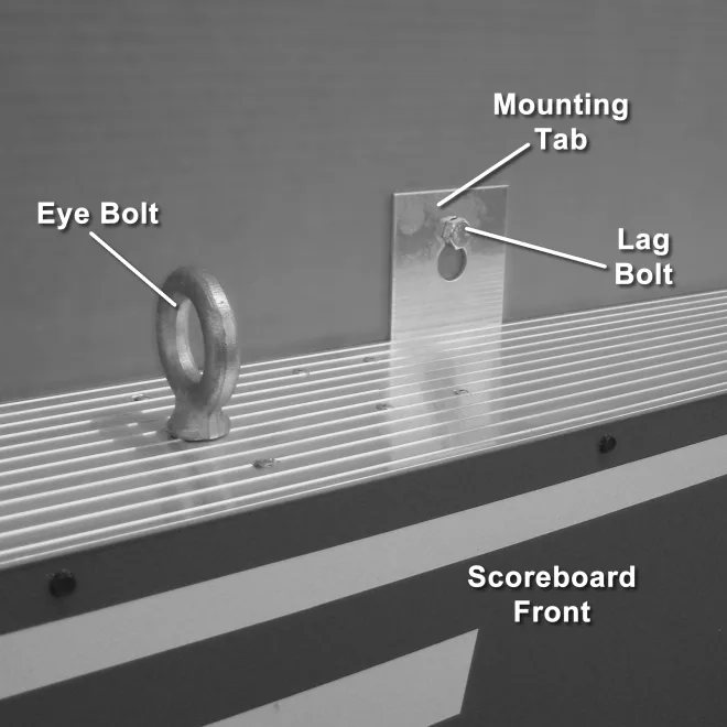
The final mechanical step is to slide the keyhole slots in the mounting tabs over the lag bolts. The lag bolts should allow the tabs to slip down into a position where the bolt heads prevent any forward shifting.
If you've followed the process as it was presented in this document, you will already have electrical receptacles and data cabling (if used) in place. At this point you should plug the scoreboard's power cord into the power receptacle. If you are hard-wiring the data cable, connect the plugs to the input ports on top of the scoreboard. The section that follows will discuss how to connect the control console and test the system.
Connections at the Control Consoles
The standard control consoles packaged with this scoreboard are powered through a typical three-prong AC power cord. At the point of operation, the console requires grounded power receptacles.
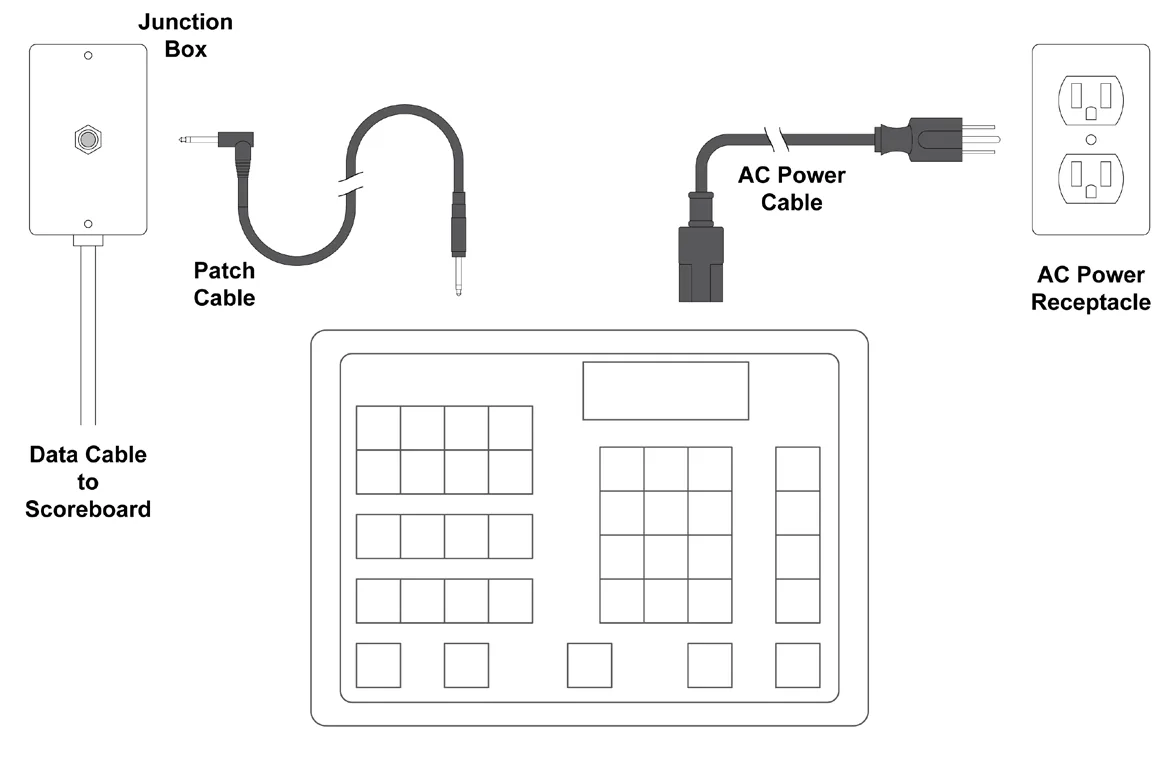
If your scoreboard package includes the ScoreLink RF Communications system, the power receptacles may be the only consideration on the control console side of the installation process. For details about ScoreLink, consult the documentation that ships with the product. Otherwise use the stereo patch cables to plug the console into the junction boxes.
TESTING, OPERATION, AND ONGOING CARE
After all power, data, and other connections are in place, it is time to test the scoreboard. Apply power to the scoreboard first. Although there is no harm in powering the consoles first, powering the scoreboard first will cause the digit displays to remain blank. Any LEDs (other than Electronic Team Names, which will initially power up with GUEST and HOME showing) that are illuminated on the scoreboard in this condition would indicate a problem at the scoreboard.
Next, power up the consoles and, for wired setups, connect a data port on the back of each console to the corresponding junction box (one for the main scoreboard, one for the stat panels) using the stereo patch cables. The scoreboard should begin showing data within a few seconds. Make sure all the buttons on the consoles and all displays on the scoreboard are responsive. You may need to consult the documentation that ships with the consoles to test certain features.
For scoreboards with Clock features, set the Clock to count down the final 30 seconds of a Period. If your scoreboard includes a Horn, it will (by default) sound when the Clock reaches 0.
Scheduled Testing and Maintenance
The scoreboard does not require scheduled maintenance procedures. However, it is important to check for problems prior to a game. We recommend running through the tests described above between two and four weeks prior to the start of a season (or anytime you plan to use the scoreboard after a gap of more than a month). During the season, test out the scoreboard the day before each game.
After the Game, and After the Season
Whenever you are not using your scoreboard, use the disconnect switch to cut power to the sign. You should unplug the control consoles from their power source and from the data cables as well. It is not necessary to take steps beyond this, even if the scoreboard will not be used for several months.
MAINTENANCE
We hope your scoreboard provides years of trouble free service. In the event of a problem, the material that follows will provide some information about contacting technical support as well as some details about the parts inside your scoreboard.
Contacting Technical Support
Our support staff is available via phone or e-mail Monday through Friday 8:00 through 5:00 Eastern. Our web address and phone number is printed at the bottom of this page. When contacting Electro-Mech for support, it helps to have the scoreboard model (LX2556) handy as well as the version of the software running on your control console. The console software version flashes briefly (for about 3 seconds) on the console's LCD display when you first apply power to it.
If you are reading this manual in search of help with a different scoreboard model, for outdoor scoreboards, you can find the model number printed on a metal plate attached to the back of the scoreboard cabinet near where the power enters. For indoor scoreboards, the model number is usually printed on a label at the top center of the cabinet near the attachment point for the power cable. If your console cannot display its software version, you can find useful information printed on the bottom of the console box.
Besides model numbers and software versions, the most important information to have is an exact description of what parts of your scoreboard are working and what parts are not working. The best person to make contact is someone who has seen the problem first hand. Better yet, give us a call when you are there at the scoreboard and can walk through a few simple tests with one or our technicians.
Scoreboard problems are rarely so complicated that diagnosing them requires skills beyond using a screwdriver and a ladder. Similarly, replacing parts is straightforward process that does not require complex tools or special knowledge.
Parts Exchange
If, after working with our support staff, you discover that a part needs to be serviced or replaced, the next step is to send the part to Electro-Mech for repair. During the warranty period, we repair parts and return them via UPS ground service at no charge. We can ship parts via overnight service for an additional charge. For work that falls outside of the warranty terms, we can, upon request, provide an estimate of repair costs on returned parts before performing the work. The typical turnaround on repair work is less than three business days
Electro-Mech maintains a supply of common parts for immediate shipment. Some customers choose to purchase new parts for immediate use and will later send old parts back to us to be repaired and returned as "backup" stock. In some cases our support plans include the option for shipping replacement parts to the customer once our service staff has identified a problem. The customer will then return the damaged part after receiving the replacement. Electro-Mech requires a valid credit card number before initiating a shipment of this type. We do not apply charges to the card unless the customer does not return parts within ten days or if the returned parts require work outside of our warranty terms.
Our shipping address:
Electro-Mech Scoreboard Co. 72 Industrial Blvd. Wrightsville, GA 31096
Location of Serviceable Parts
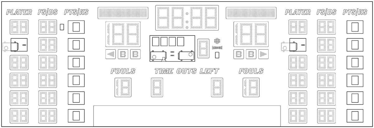
The power and driver components for the main scoreboard are located behind the Period panel in the middle of the scoreboard cabinet. The ScoreLink receiver (if purchased) and the Horn are located to the right of the Period digit and are accessed by removing that digit. Each stat panel section has a power supply located behind the second Player digit pair and LX drivers located behind each Points/Kills digit pair.
LED Displays
The LED displays (but not individual LEDs) are field replaceable parts. Each LED is soldered to a printed circuit board (PCB) which is, in turn, attached to a protective metal mask. The mask assembly is attached to the scoreboard face with machine screws. You will need a 1/4-inch nut driver to remove these screws.
Step-By-Step:
- Disconnect power to the scoreboard before performing any service work.
- Remove the machine screws from the metal mask, leaving for last one of the screws along the top of the mask.
- Support the mask with one hand as you remove the final screw.
- Rotate the mask so that you can see the PCB (or PCBs) behind it and the cable connections along the back side.
- Unplug the ribbon cables from the PCBs.
- Set the mask aside and save the screws for later.
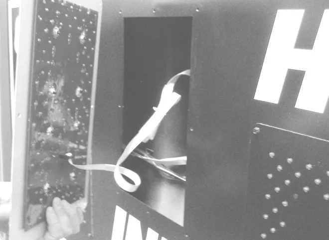
If your purpose in removing the mask was to provide access to the components behind it, you may skip the next part about removing and replacing the LED printed circuit board.
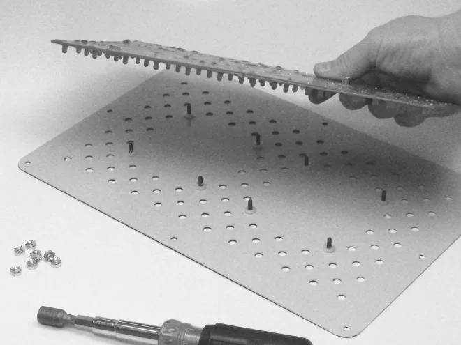
The LED display circuit board is held to the mask by several nuts, which you can remove using a 3/8-inch nut driver. Some single digit PCBs fit into their masks in two orientations, 180 degrees apart. Unless the digit shares the mask with another PCB, either orientation is fine within the mask. But you have to be careful to keep the whole assembly right side up with you return it to the scoreboard.
Power Supplies and Fuses
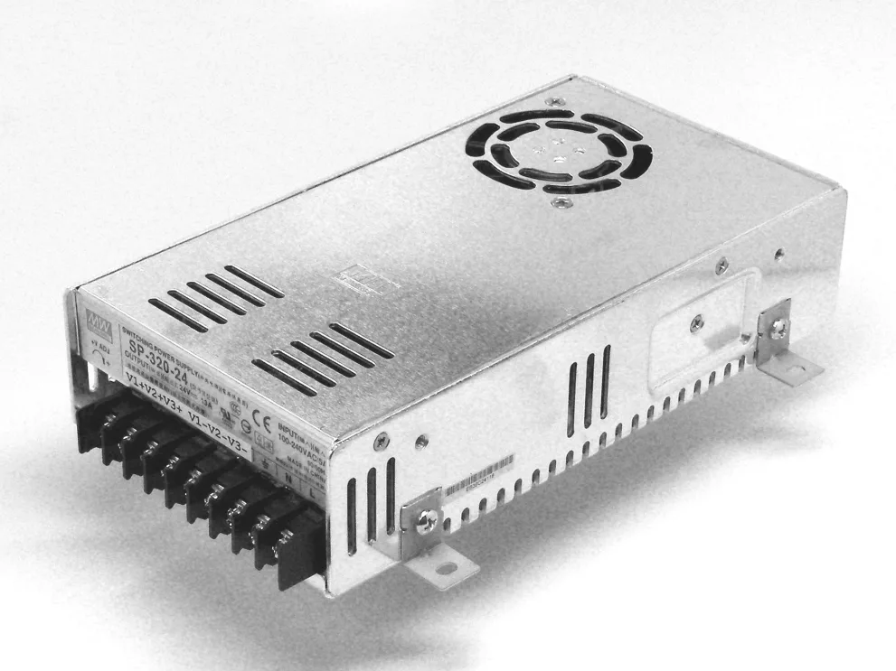
AC power enters the scoreboard through the power cord attached to the top of the scoreboard cabinet. From here, power is routed to the various power supply modules in the scoreboard. When this scoreboard is made WITHOUT Electronic Team Names, it uses three Mean Well SP-320-24 power supply modules. A 5 amp fuse is located next to each power supply module. AC line passes through these fuses on the way to each module. If the scoreboard includes Electronic Team Names, a fourth power supply module, Mean Well model SP-320-5, is added to the central chassis and the fuse there changes from 5 amps to 10 amps. All fuses in the scoreboard are AG style that should only be replaced with fuses of the same style and rating.
Each stat panel section (Guest and Home) is powered by a Mean Well SP-320-5 power supply module. Each of these modules can be accessed by removing the second Player Number digit pair on the stat panel face.
Power connections are made along a row of screw terminals on one side of each power supply module. All three Mean Well SP-320-24 power modules should be set to18.9 VDC output level. If an SP-320-5 module is present to power the ETN displays, it should provide 5 VDC output. If you replace one of the power supply modules, check the output voltage to make certain it is set correctly.
LX Drivers
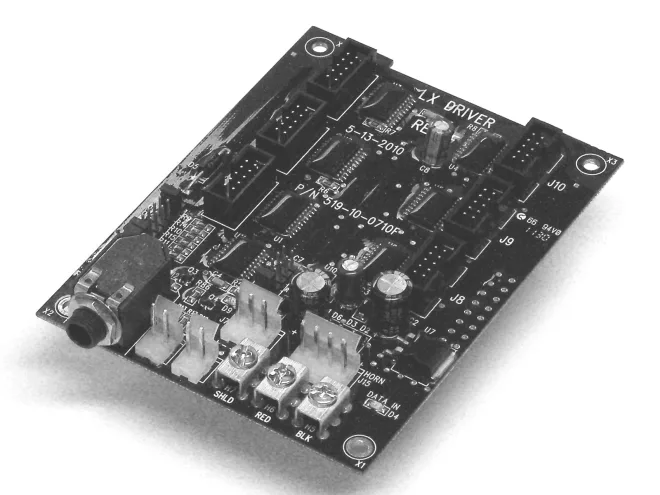
The LX Driver circuit boards do the work of interpreting data sent to the scoreboard and sending signals out to the LEDs so that the right lights come on at the right time. Each LX Driver handles a specific set of functions on the scoreboard and supplies signals to the LED displays via ribbon cables. Data flows through the LX Drivers in a specific order, from left to right as they are arranged in the chassis. The functions supported by each LX are listed below, with the order of data flow following from left to right.
| Central Chassis LX Drivers | |||||||||
| Connector | LX17 | LX4 | LX24 | ||||||
| J2 (Data In) | From ScoreLink | ||||||||
| To Data Output Port | |||||||||
| J3 (Data Out) | To LX4 | To LX24 | |||||||
| or to ETN Driver | |||||||||
| Game Clock Minutes | Right Team Fouls | ||||||||
| J4 (Word 1 Low) | Right Score Units | ||||||||
| Units | Units, Tens | ||||||||
| Game Clock Minutes | Right Score Tens, | ||||||||
| J5 (Word 1 High) | |||||||||
| Tens | Hundreds | ||||||||
| Game Clock | Left Team Fouls | ||||||||
| J6 (Word 2 Low) | Left Score Units | ||||||||
| Seconds Units | Units, Tens | ||||||||
| J7 (DC Power In) | 18.9 VDC | 18.9 VCD | 18.9 VDC | ||||||
| Right Bonus 1, | |||||||||
| J8 (Word 3) | Period | Right TOL | |||||||
| Bonus 2, Poss | |||||||||
| Game Clock | Left Score Tens, | ||||||||
| J9 (Word 2 High) | |||||||||
| Seconds Tens | Hundreds | ||||||||
| Left Bonus 1, | |||||||||
| J10 (Word 4) | Colon/Decimal | Left TOL | |||||||
| Bonus 2, Poss | |||||||||
| J15 (Horn) | Horn | ||||||||
| H5/BLK (Data In) | From Data Input Port | From LX17 | From LX4 | ||||||
| H6/RED (Data In) | From Data Input Port | From LX17 | From LX4 | ||||||
| H5/SHLD (Data In) | From Data Input Port | From LX17 | From LX4 | ||||||
| Jumper Pins | LX17 | LX4 | LX24 | ||||||
| H13 (J4/J5 Blanking) | X | ||||||||
| H16 (J4/J5 Blanking) | X | X | |||||||
| H14 (J6/J9 Blanking) | X | ||||||||
| H17 (J6/J9 Blanking) | X | ||||||||
| H15 (Blank/Stat) | |||||||||
| H18 (Lamp/Stat) | |||||||||
| H3 (Horn2 No Dim) | X | X | X | ||||||
| H11 (Spare Shunt) | X | X | X | ||||||
| H19 (Not Used) | |||||||||
| H1 (Memory Ret.) | |||||||||
| H2 (Group +1) | X | X | X | ||||||
| H4 (Bank +2) | X | ||||||||
| H12 (Bank +1) | X |
If your scoreboard includes Electronic Team Names, the ETN0 driver will be located in the central chassis to the right of the LX24 driver. The J14 connector supplies ETN data to the team name display on the right side. The J10 connector supplies ETN data to the team name display on the left side.
Data for the stat panels comes from a separate control console and enters the scoreboard via its own data port (or ScoreLink receiver). This data flows from the top line of stats on the left side, down line by line to the bottom, then over to the top line of stats on the right side, down line by line to the bottom, and finally to the output port. Each line on a stat panel has its own LX driver to control the six digits.
| Left Side Stat Panel LX Drivers | |||||||||||||||||||
| Connector | LX48 | LX49 | LX50 | LX51 | LX52 | LX58 | |||||||||||||
| From | |||||||||||||||||||
| J2 (Data In) | |||||||||||||||||||
| ScoreLink | |||||||||||||||||||
| J3 (Data Out) | To LX49 | To LX50 | To LX51 | To LX52 | To LX58 | To LX53 | |||||||||||||
| J4 (Word 1 Low) | 1 Player Tens | 2 Player Tens | 3 Player Tens | 4 Player Tens | 5 Player Tens | 6 Player Tens | |||||||||||||
| J5 (Word 1 High) | 1 Player Units | 2 Player Units | 3 Player Units | 4 Player Units | 5 Player Units | 6 Player Units | |||||||||||||
| J6 (Word 2 Low) | 1 Fouls Tens | 2 Fouls Tens | 3 Fouls Tens | 4 Fouls Tens | 5 Fouls Tens | 6 Fouls Tens | |||||||||||||
| J7 (DC Power In) | 18.9 VDC | 18.9 VDC | 18.9 VDC | 18.9 VDC | 18.9 VDC | 18.9 VDC | |||||||||||||
| J8 (Word 3) | 1 Fouls Units | 2 Fouls Units | 3 Fouls Units | 4 Fouls Units | 5 Fouls Units | 6 Fouls Units | |||||||||||||
| J9 (Word 2 High) | 1 Points Tens | 2 Points Tens | 3 Points Tens | 4 Points Tens | 5 Points Tens | 6 Points Tens | |||||||||||||
| J10 (Word 4) | 1 Points Units | 2 Points Units | 3 Points Units | 4 Points Units | 5 Points Units | 6 Points Units | |||||||||||||
| J15 | |||||||||||||||||||
| From Data | |||||||||||||||||||
| H5/BLK (Data In) | From LX48 | From LX49 | From LX50 | From LX51 | From LX52 | ||||||||||||||
| Input Port | |||||||||||||||||||
| From Data | |||||||||||||||||||
| H6/RED (Data In) | Input Port | From LX48 | From LX49 | From LX50 | From LX51 | From LX52 | |||||||||||||
| From Data | |||||||||||||||||||
| H5/SHLD (Data In) | From LX48 | From LX49 | From LX50 | From LX51 | From LX52 | ||||||||||||||
| Input Port | |||||||||||||||||||
| Jumper Pins | LX48 | LX49 | LX50 | LX51 | LX52 | LX58 | |||||||||||||
| H13 (J4/J5 Blanking) | |||||||||||||||||||
| H16 (J4/J5 Blanking) | |||||||||||||||||||
| H14 (J6/J9 Blanking) | |||||||||||||||||||
| H17 (J6/J9 Blanking) | |||||||||||||||||||
| H15 (Blank/Stat) | X | X | X | X | X | X | |||||||||||||
| H18 (Lamp/Stat) | X | X | X | X | X | X | |||||||||||||
| H3 (Right Team) | |||||||||||||||||||
| H11 (Spare Shunt) | |||||||||||||||||||
| H19 (Not Used) | |||||||||||||||||||
| H1 (Memory Ret.) | |||||||||||||||||||
| H2 (Group +1) | X | X | |||||||||||||||||
| H4 (Bank +2) | X | X | |||||||||||||||||
| H12 (Bank +1) | X | X | X |
| Right Side Stat Panel LX Drivers | ||||||
| Connector | LX53 | LX54 | LX55 | LX56 | LX57 | LX59 |
| J2 (Data In) | ||||||
| To Data | ||||||
| J3 (Data Out) | To LX54 | To LX55 | To LX56 | To LX57 | To LX59 | |
| Output Port | ||||||
| J4 (Word 1 Low) | 1 Player Tens | 2 Player Tens | 3 Player Tens | 4 Player Tens | 5 Player Tens | 6 Player Tens |
| J5 (Word 1 High) | 1 Player Units | 2 Player Units | 3 Player Units | 4 Player Units | 5 Player Units | 6 Player Units |
| J6 (Word 2 Low) | 1 Fouls Tens | 2 Fouls Tens | 3 Fouls Tens | 4 Fouls Tens | 5 Fouls Tens | 6 Fouls Tens |
| J7 (DC Power In) | 18.9 VDC | 18.9 VDC | 18.9 VDC | 18.9 VDC | 18.9 VDC | 18.9 VDC |
| J8 (Word 3) | 1 Fouls Units | 2 Fouls Units | 3 Fouls Units | 4 Fouls Units | 5 Fouls Units | 6 Fouls Units |
| J9 (Word 2 High) | 1 Points Tens | 2 Points Tens | 3 Points Tens | 4 Points Tens | 5 Points Tens | 6 Points Tens |
| J10 (Word 4) | 1 Points Units | 2 Points Units | 3 Points Units | 4 Points Units | 5 Points Units | 6 Points Units |
| J15 | ||||||
| H5/BLK (Data In) | From LX58 | From LX53 | From LX54 | From LX55 | From LX56 | From LX57 |
| H6/RED (Data In) | From LX58 | From LX53 | From LX54 | From LX55 | From LX56 | From LX57 |
| H5/SHLD (Data In) | From LX58 | From LX53 | From LX54 | From LX55 | From LX56 | From LX57 |
| Jumper Pins | LX53 | LX54 | LX55 | LX56 | LX57 | LX59 |
| H13 (J4/J5 Blanking) | ||||||
| H16 (J4/J5 Blanking) | ||||||
| H14 (J6/J9 Blanking) | ||||||
| H17 (J6/J9 Blanking) | ||||||
| H15 (Blank/Stat) | X | X | X | X | X | X |
| H18 (Lamp/Stat) | X | X | X | X | X | X |
| H3 (Right Team) | X | X | X | X | X | X |
| H11 (Spare Shunt) | ||||||
| H19 (Not Used) | ||||||
| H1 (Memory Ret.) | ||||||
| H2 (Group +1) | X | X | ||||
| H4 (Bank +2) | X | X | ||||
| H12 (Bank +1) | X | X | X |
LIMITED WARRANTY STATEMENT
Electro-Mech Scoreboard Company Standard Equipment Warranty and Limitation of Liability for Scoreboards and Accessories Sold in the United States
Warranty Coverage
Electro-Mech warrants to the original end-user that the Equipment will be free from Defects (as defined below) in materials and workmanship for a period of five years from the date of invoice. Electro-Mech's obligation under this warranty is limited to, at Electro-Mech's option, replacing or repairing any Equipment or Part thereof that is found by Electro-Mech not to conform to the Equipment’s specifications. Any defective Part must be returned to Electro-Mech for repair or replacement. Equipment determined not to conform to specifications will be repaired or replaced and returned to purchaser with standard ground service transportation charges prepaid. Replacement Parts or Equipment will be new or serviceably used, comparable in function and performance to the original Parts or Equipment, and warranted for the remainder of the warranty period. Purchasing additional Parts or Equipment from Electro-Mech does not extend this warranty period.
Defects shall be defined as follows. With regard to the Equipment (excepting LEDs), a "Defect" refers to a material variance from the design specifications that prohibits the Equipment from operating for its intended use. With respect to LEDs, "Defects" are defined as LEDs that cease to emit light. The limited warranty provided by Electro- Mech does not impose any duty or liability upon Electro-Mech for partial LED degradation.
This limited warranty is not transferable.
Exclusions from Warranty Coverage
The limited warranty provided by Electro-Mech does not impose any liability upon Electro-Mech for:
- Damage caused by the unauthorized adjustment, repair, or service of the Equipment by anyone other than personnel of Electro-Mech or its authorized repair agents.
- Rental fees or other costs associated with lifts, cranes, or other tools and services used to access the Equipment.
- Damage caused by the failure to provide a continuously suitable environment, including, but not limited to (i) neglect or misuse (ii) a failure or surges of electrical power (iii) any cause other than ordinary use.
- Damage caused by vandalism, fire, flood, earthquake, water, wind, lightning, or other natural disaster, or by any other event beyond Electro-Mech’s reasonable control.
- Costs associated with replacement of communication methods including but not limited to, wireless systems, copper wire, fiber optic cable, conduit, or trenching for the purpose of overcoming local site interference.
- Any statements regarding products or services made by salesmen, dealers, distributors, or agents, unless such statements are in a written document signed by an officer of Electro-Mech.
Limitation of Liability
In no event shall Electro-Mech be liable for any special, consequential, incidental, or exemplary damages arising out of or in any way connected with the Equipment or otherwise, including but not limited to damages for lost profits, cost of substitute or replacement equipment, down time, lost data, or injury to property, or any damages or sums paid by the purchaser to third parties.