
Home / Documentation / Accessory manual
Download the original PDF (389 kB)
This page reproduces the text of the PDF above without alteration, so the document can be read, searched and linked to directly.
Replacement Procedure
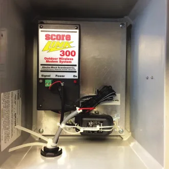
Old ScoreLink Receiver Assembly (shown mounted in NEMA box)
1. DISCONNECT POWER TO THE SCOREBOARD!
2. Open the gray, weatherproof NEMA box mounted near your Scoreboard Display.
3. If you are replacing an SL-300 receiver, remove the green “Signal” connector from the red and black data wires and discard it. If you have a newer ScoreLink model, you may reuse the white connector (attached to the J3 pins on the old PCB). In either case, unplug the data wires from the ScoreLink Receiver.
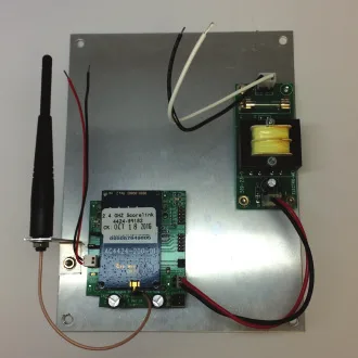
New ScoreLink Receiver Assembly with PCB-style power supply
4. Disconnect the AC power wires from the old assembly. SL-300 systems included a 9VDC transformer and duplex receptacle, neither of which are used with newer systems. The AC power wires are typically white and black, although some older systems used a different color code.
5. Remove the four (4) screws holding the metal plate inside the NEMA box, and extract the old ScoreLink Receiver Assembly.
6. Mount the new ScoreLink Receiver Assembly inside the NEMA box with the four (4) screws.
7. Splice the red and black data wires from the new data connector to the red and black data wires from the original cabling that enters the NEMA box through the knockout.
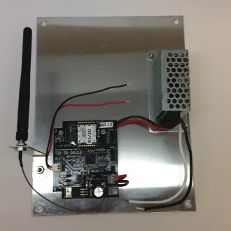
New ScoreLink Receiver Assembly with enclosed power supply module
8. Plug the new data connector onto the J3 connector of the new Modem Interface Card, making certain to use the center and output (O) pins.
9. Splice your old AC wires to the wires coming from the new power supply ─ black to black (hot) and white to white (neutral). Older systems may use a red wire for AC neutral.
Page 1 of 1
Electro-Mech Engineering / 2016-Nov-02