
Home / Documentation / Accessory manual
Download the original PDF (125 kB)
This page reproduces the text of the PDF above without alteration, so the document can be read, searched and linked to directly.
ELECTRO-MECH SCOREBOARD CO. SL-230 / 330 RF MODEM INSTALLATION MANUAL
Thank you for choosing an Electro-Mech Scoreboard for your athletic complex. We are confident that this product will give many years of reliable service.
RF Exposure Warning for Mobile Equipment
Warning: To satisfy FCC RF exposure requirements for mobile type transmitting devices, a separation distance of 20 cm or more should be maintained between the antenna of this device and persons during operation, with exception of hands wrist, feet, and ankles. To ensure compliance, operations at a closer distance than this distance is prohibited.
SL-330-DTXK SPECIFICATIONS
GENERAL: This FCC compliant accessory includes a transmitter assembly, 10 ft. extension cable, and a wall mount DC power supply.
DIMENSIONS: 5.5” L x 3.6” W x 2.7” H
WEIGHT: 0.80 lbs
POWER REQUIREMENTS: 115 VAC, 0.25 A, 60 Hz
SL-330-RRXK SPECIFICATIONS
GENERAL: This FCC compliant accessory includes a receiver assembly (receiver installed in a NEMA 4X enclosure) and receiver assembly mounting hardware.
RECEIVER ASSEMBLY DIMENSIONS (not including mounting hardware): 10.50” H x 9.30” W x 5.20” D)
RECEIVER ASSEMBLY WEIGHT: 6.92 lbs
RECEIVER ASSEMBLY POWER REQUIREMENTS: 115 VAC, 0.25 A, 60 Hz
WARRANTY: Five year limited warranty.
SL-230-DRXK SPECIFICATIONS
GENERAL: This FCC compliant accessory includes a receiver assembly, 10 ft. extension cable, and a wall mount DC power supply.
DIMENSIONS: 5.5” L x 3.6” W x 2.7” H
WEIGHT: 0.80 lbs
POWER REQUIREMENTS: 115 VAC, 0.25 A, 60 Hz
SL-330-DTXK PRODUCT DESCRIPTION
The SL-330-DTX is a 2.4 GHz RF modem transmitter for use with Electro-Mech Scoreboard Co. outdoor MM, MP, or LED control consoles. This accessory allows the transmission of instructions from an Electro-Mech Scoreboard Co. MM or MP series control console without the connection of a control cable between the console and the scoreboard. The SL-330-DTX transmitter sends radio frequency signals that contain the console instructions through the air to another RF modem (receiver). The receiver detects the radio frequency signals and passes the instructions to the scoreboard. The SL- 330-DTX is packaged for indoor use and is installed adjacent to the control console. The SL-330-DTX transmitter should be installed with no line of sight obstructions to the receiver. Non-metallic obstructions may decrease the range. The radio frequency signals can not pass through metal objects.
Multiple scoreboards can be controlled with one control console, a SL-330-DTXK, and multiple compatible receivers.
Disregard the section of the scoreboard owner’s manual titled Control Cable Installation or Installing the Control Cable.
SL-330-BTXK PRODUCT DESCRIPTION
The SL-330-DTXK is a 2.4 GHz RF modem transmitter embedded inside Electro-Mech Scoreboard Co. outdoor MM, MP, or LED control consoles. This accessory allows the transmission of instructions from an Electro-Mech Scoreboard Co. MM or MP series control console without the connection of a control cable between the console and the scoreboard. The transmitter sends radio frequency signals that contain the console instructions through the air to another RF modem (receiver). The receiver detects the radio frequency signals and passes the instructions to the scoreboard. The console should be installed with the transmitter antenna in line of sight of the receiver without obstructions. The antenna should be rotated so that the end of the antenna points upward. Non-metallic obstructions may decrease the range. The radio frequency signals can not pass through metal objects.
Multiple scoreboards can be controlled with one control console with a SL-330-BTXK and multiple compatible receivers.
Disregard the section of the scoreboard owner’s manual titled Control Cable Installation or Installing the Control Cable.
SL-330 RRXK PRODUCT DESCRIPTION
The SL-330-RRXK is a 2.4 GHz RF modem receiver for use with Electro-Mech Scoreboard Co. outdoor MM, MP, or LED scoreboards. This accessory allows the scoreboard to receive instructions from an Electro-Mech Scoreboard Co. MM or MP series control console without the connection of a control cable between the console and the scoreboard. The control console instructions are sent via a compatible RF modem transmitter embedded in the control console or in a separate unit connected to the control console. The transmitter sends radio frequency signals that contain the console instructions through the air to another RF modem (receiver). The receiver detects the radio frequency signals and passes the instructions to the scoreboard. The SL-330- RRXK is packaged for outdoor use and is installed adjacent to the scoreboard. The receiver should be installed within 750 ft. of the transmitter with no line of sight obstructions. Non-metallic obstructions may decrease the range. The radio frequency signals can not pass through metal objects.
Multiple scoreboards can be controlled with one control console, a compatible RF modem transmitter, and multiple SL-330-RRXK receivers. Additional units are available for purchase from Electro-Mech Scoreboard Co.
The SL-330-RRXK does not replace the need to run power cables to the scoreboard. Disregard the section of the scoreboard owner’s manual titled Control Cable Installation or Installing the Control Cable.
SL-230-DRXK PRODUCT DESCRIPTION
The SL-230-DRX is a 2.4 GHz RF modem receiver for use with Electro-Mech Scoreboard Co. indoor LED scoreboards. This accessory allows the scoreboard to receive instructions from an Electro-Mech Scoreboard Co. MM or MP series control console without the connection of a control cable between the console and the scoreboard. The control console instructions are sent via a compatible RF modem transmitter embedded in the control console or in a separate unit connected to the control console. The transmitter sends radio frequency signals that contain the console instructions through the air to the SL-230-DRX. The SL-230-DRX receiver detects the radio frequency signals and passes the instructions to the scoreboard. The SL-230-DRX is packaged for indoor use and is installed adjacent to the scoreboard. The SL-230-DRX receiver should be installed with no line of sight obstructions to the transmitter. Non- metallic obstructions may decrease the range. The radio frequency signals can not pass through metal objects.
Multiple scoreboards can be controlled with one control console, a compatible RF modem transmitter, and multiple SL-230-DRXK receivers.
Disregard the section of the scoreboard owner’s manual titled Control Cable Installation or Installing the Control Cable.
CONTROL CONSOLE WITH SL-330-BTXK INSTALLATION
Installation of the SL-330-BTXK consists of locating the control console at the scorekeeper’s table, and making the proper electrical connections. 1.Place the control console on a flat surface. If the scoreboard is outdoors, it may be necessary to locate the control console in front of a window that provides a line of sight view of the compatible receiver at the scoreboard. 2.Rotate the antenna so that the end of the antenna points upward. 3.Plug the power cord into a grounded NEMA 5-15R 120 VAC receptacle.
SL-330-DTXK INSTALLATION
SL-330-DTXK consists of:
- SL-330-DTX transmitter
- 10 ft. stereo extension cable
- DC power supply
Installation of the SL-330-DTXK consists of locating the SL-330-DTX transmitter at the scorekeeper’s table, and making the proper electrical connections. 1.Place the SL-330-DTX transmitter on a flat surface within 10 ft. of the control console. If the scoreboard is outdoors, it may be necessary to locate the SL-330-DTX transmitter in front of a window that provides a line of sight view of the compatible receiver at the scoreboard. 2.Plug one end of the extension cable into the ¼” stereo jack on the SL-330-DTX transmitter. 3.Plug the other end into a ¼” stereo jack mounted on the control console back plate. 4.Plug the wall mount DC power supply into a grounded NEMA 5-15R 120 VAC receptacle and the male plug on the end of the attached cable into the 3.5mm jack on the SL-330-DTX transmitter.
SL-330-RRXK INSTALLATION
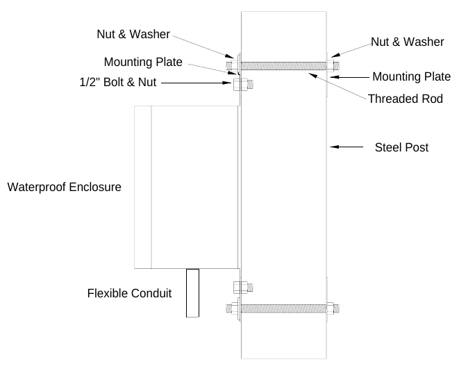
Installation of the SL-330-RRXK consists of mounting the unit at the scoreboard and making the proper electrical connections. Mount the receiver above the scoreboard on the post that is closest to the rear access panel with the provided hardware according to figure 1. Point the receiver hinged cover toward the control console location with the flexible conduit connected to the bottom of the enclosure. For scoreboards with more than one access panel, refer to the scoreboard owner’s manual to identify the access panel that the control cable would have been connected behind (listed in the section titled Control Cable Installation or Installing the Control Cable). The connections from the receiver to the scoreboard will be made behind this access panel.
Overhead Cross Section View
Side Cross Section View
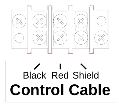
Remove the access panel. A section of flexible conduit is attached to the weatherproof enclosure. Two cables extend from the conduit. Run the cables through one of the holes in the plate below the access panel and fasten the end of the conduit to the scoreboard using the conduit nut. The data cable has three wires and is attached to Control Cable terminal block behind the scoreboard rear access panel. For scoreboards with more than one access panel, refer to the scoreboard owner’s manual for the location of the terminal block. Figure 2 shows the connections to Control Cable terminal block.
The power cable has two wires and is attached to terminal block to which the power cable wires that supply the scoreboard are connected. Refer to figures 5, 6, and 7 to determine the appropriate power connections.
Figure 3 shows the connections to the power terminal block found in our smaller outdoor MM and MP scoreboards.
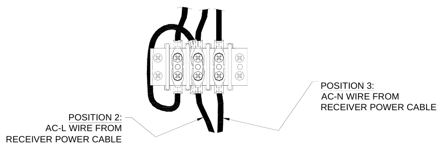
Figure 4 shows the connections to the power terminal block found in our larger outdoor MM and MP scoreboards.
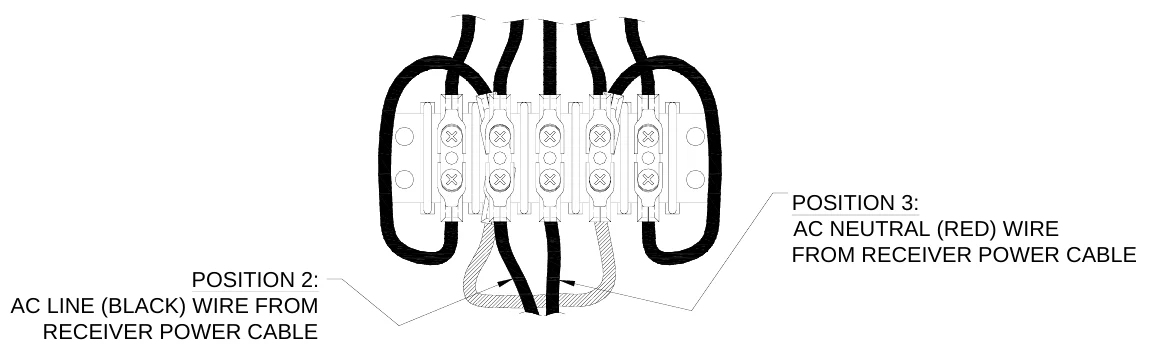
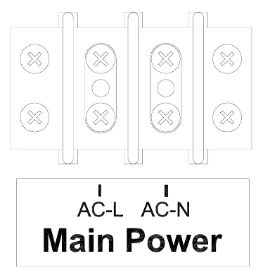
Figure 5 shows the connections to the main power terminal block inside the outdoor LED scoreboards.
IMPORTANT: After installation, make sure that conduit connectors are tight. Install the rear access panel.
While Electro-Mech Scoreboard Company does not perform installations in most states, we will make every effort to answer your installation questions. Installation should be performed by qualified personnel. In many areas there are independent installers who are experienced in Electro-Mech Scoreboard Co. product installations. You can contact Electro-Mech Scoreboard Co. to determine if we can help you locate an installer.
SL-230-DRXK INSTALLATION
SL-230-DRXK consists of:
- SL-230-DRX receiver
- 10 ft. stereo extension cable
- DC power supply
Installation of the SL-230-DRXK consists of locating the SL-230-DRX receiver on top of the scoreboard, and making the proper electrical connections. 1.Place the SL-230-DRX receiver on top of the scoreboard within 10 ft. of the ¼” stereo jack. Locate it so that there is a direct line of sight to the compatible transmitter. 2.Plug one end of the extension cable into the ¼” stereo jack on the SL-230-DRX receiver. 3.Plug the other end into a ¼” stereo jack mounted on top of the scoreboard. 4.Plug the wall mount DC power supply into a grounded NEMA 5-15R 120 VAC receptacle and the male plug on the end of the attached cable into the 3.5mm jack on the SL-230-DRX receiver.
ELECTRO-MECH SCOREBOARD CO. FIVE YEAR LIMITED WARRANTY
THE ELECTRICAL COMPONENTS OF ALL ELECTRO-MECH SCOREBOARDS ARE GUARANTEED FOR A PERIOD OF FIVE (5) YEARS FROM THE DATE OF INVOICE AGAINST DEFECTS IN WORKMANSHIP OR MATERIAL AND WILL BE REPLACED OR REPAIRED WITHOUT COST TO THE OWNER PROVIDED THE EQUIPMENT OR PARTS ARE RETURNED POSTAGE-PAID TO THE FACTORY IN WRIGHTSVILLE, GA. SHIPPING BACK TO THE OWNER WILL BE VIA UPS GROUND SERVICE EXCEPT WHEN AIR OR SPECIAL METHOD OF RETURN IS SPECIFIED BY THE OWNER, IN WHICH CASE SHIPPING WILL BE FREIGHT COLLECT.
THIS WARRANTY DOES NOT INCLUDE LABOR CHARGES INCURRED IN THE REMOVAL OF COMPONENT PARTS, SERVICE CALLS, OR DAMAGES RESULTING FROM IMPROPER INSTALLATION, IMPROPER OPERATION, OR PROBLEMS CAUSED BY ANY REPAIR, ALTERATION OR MODIFICATION OF THE SCOREBOARD NOT PERFORMED BY ELECTRO-MECH.
EQUIPMENT WHICH IS SUBJECTED TO ACCIDENT, NEGLECT, ABUSE, MISUSE OR OTHER NATURAL DISASTERS, INCLUDING BUT NOT LIMITED TO FIRE, WIND, LIGHTNING, OR FLOOD, IS NOT COVERED BY THIS GUARANTEE.