
Home / Documentation / Accessory manual
Download the original PDF (116 kB)
This page reproduces the text of the PDF above without alteration, so the document can be read, searched and linked to directly.
OWNER’S HANDBOOK
Thank you for choosing an Electro-Mech Scoreboard for your athletic complex. We are confident that your new scoreboard will give many years of reliable service.
Rev. 3 Revised: 01/23/2006
FCC COMPLIANCE STATEMENT
This equipment has been tested and found to comply with the limits for a class B digital device, pursuant to part 15 of the FCC Rules. These limits are designed to provide reasonable protection against harmful interference in a residential installation. This equipment generates, uses and can radiate radio frequency energy and if not installed and used in accordance with the instructions, may cause harmful interference to radio communications. However, there is no guarantee that interference will not occur in a particular installation. If this equipment does cause harmful interference to radio or television reception, which can be determined by turning the equipment off and on, the user is encouraged to try to correct the interference by one or more of the following measures:
* Reorient or relocate the receiving antenna.
* Increase the separation between the equipment and receiver.
* Connect the equipment into an outlet on a circuit different from that to which the receiver is connected.
* Consult the dealer or an experienced radio/TV technician for help.
This equipment has been certified to comply with the limits for a class B computing device, pursuant to FCC Rules. In order to maintain compliance with FCC regulations, shielded cables must be used with this equipment. Operation with non-approved equipment or unshielded cables is likely to result in interference to radio and TV reception. The user is cautioned that changes and modifications made to the equipment without the approval of manufacturer could void the user’s authority to operate this equipment.
SCORELINK 200 RF MODEM SYSTEM SPECIFICATIONS
GENERAL: This FCC compliant accessory includes the transmitter, receiver, two DC power cube supplies, and a custom carrying case for the transmitter, transmitter DC power cube supply, scoreboard control console, and control console accessories.
DIMENSIONS: transmitter: 2.64” L x 6.9” H x 2.1” D 2.1” D
receiver: 2.64” L x 6.9” H x
WEIGHT: transmitter: 0.42 lbs
receiver: 0.42 lbs
POWER REQUIREMENTS: transmitter - 115 VAC, 0.1 A, 60 Hz. receiver - 115 VAC, 0.1 A, 60 Hz
WARRANTY: Five year limited warranty.
PRODUCT DESCRIPTION
The SCORELINK 200 RF MODEM SYSTEM is an accessory that allows an Electro- Mech Scoreboard Co. MM or MP series control console to send instructions to an Electro-Mech Scoreboard Co. MM or MP series indoor scoreboard without the connection of a control cable between the console and the scoreboard. The SCORELINK 200 RF MODEM SYSTEM consists of two units: a transmitter and a receiver. The transmitter sends radio frequency signals that contain the console instructions through the air to the receiver. The receiver detects the radio frequency signals and passes the instructions to the scoreboard. The transmitter is installed near the control console. The receiver is installed adjacent to the scoreboard. The receiver should be installed within 750 ft. of the transmitter with no line of sight obstructions.
The SCORELINK 200 RF MODEM SYSTEM consists of a transmitter and a receiver which are factory set to the same channel. There are eight factory set channels available. Contact the factory if the site requirements exceed the eight channel capacity. Multiple scoreboards can be controlled with one control console, one transmitter, and multiple receivers if all units are on the same channel. Additional transmitters and receivers are available for purchase from Electro-Mech Scoreboard Co. Transmitters and receivers with different channel numbers will not work together. Multiple transmitters with identical channel numbers in close proximity may cause interference problems.
While the SCORELINK 200 RF MODEM SYSTEM is intended to eliminate the control cable between the scoreboard and the control console on Electro-Mech Scoreboard MM and MP series scoreboards, it does not replace the need to supply power to the scoreboard. Disregard the section of the scoreboard owner’s manual on installing the control cable.
INSTALLATION
Installation of the SCORELINK 200 RF MODEM SYSTEM consists of mounting the receiver at the scoreboard, locating the transmitter at the scorekeeper’s table, and making the proper electrical connections.
Transmitter Installation The preferred method of installation is the transmitter located within direct line of sight of the scoreboard with the top of the transmitter pointing up. Objects between the transmitter and the receiver will tend to decrease the system operating range. The transmitter signal will not pass through metal, so a large metal structure between the transmitter and receiver may prevent the system from working. However, the signal may bounce off metal objects in an indirect path to the receiver and allow the system to work.
The transmitter can be freestanding using the supplied mounting brackets as shown in figure 1. It can also be mounted on a wall using screws. It may be possible to operate with the transmitter placed on a flat surface like a table without the mounting bracket.
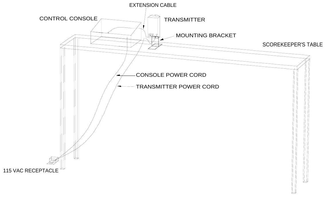
A ¼” stereo extension cable is provided to make the connection between the control console and the transmitter. Plug one end of the cable into the ¼” stereo jack (Signal) on the transmitter and plug the other end into one of the ¼” stereo jacks on the rear of the control console. The transmitter operates with a DC power cube supply. Plug the male
plug into the power jack on the transmitter and plug the power cube supply into a standard 115 VAC (NEMA 5-15R) receptacle. The modem uses 0.1A of current.
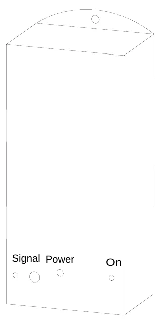
Figure 2 shows the transmitter jacks and indicators.
Receiver Installation The receiver has a factory attached mounting bracket and data cable. The receiver should be mounted on top of the scoreboard approximately six inches to the right of the scoreboard’s attached power cord. Use a drill with a hex head bit to attach the mounting bracket to the scoreboard using the four self-tapping sheet metal screws which are provided. When installed, the front of the receiver should be flush with the front of the scoreboard. Plug the data cable’s ¼” stereo plug into the ¼” stereo jack adjacent to the scoreboard’s power cord. The receiver also operates with a DC power cube supply. Plug the male plug into the power jack on the receiver and plug the power cube supply into a standard 115 VAC (NEMA 5-15R) receptacle. If possible this should be the same receptacle that the scoreboard is plugged into so that the power to the scoreboard and receiver are turned on at the same time. The modem uses 0.1A of current. Figure 3 shows a typical installation.
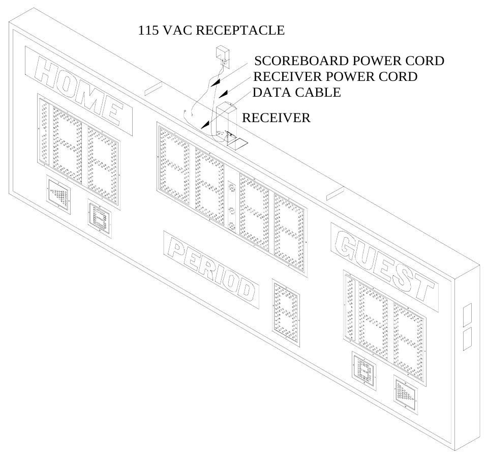
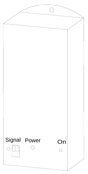
Figure 4 shows the receiver jacks and indicators.
While Electro-Mech Scoreboard Company does not perform installations in most states, we will make every effort to answer your installation questions. Installation should be performed by qualified personnel. In many areas there are independent installers who are experienced in Electro-Mech Scoreboard Co. product installations. You can contact Electro-Mech Scoreboard Co. to determine if we can help you locate an installer.
OPERATION
After installing the scoreboard and the SCORELINK 200 RF MODEM SYSTEM, turn on the power to the scoreboard, the control console, and the SCORELINK 200. The scoreboard should turn on and the operator should be able to control it from the console. Refer to the scoreboard owner’s manual for console operation.
You should reset the scoreboard each time that it is turned on. Test out all the functions to ensure that the scoreboard is operating properly. Electro-Mech Scoreboard Company strongly advises that you unplug the control console and the transmitter and turn the power to the scoreboard off when the scoreboard is not in use. The control console can’t turn the scoreboard off. This action will help protect the scoreboard, control console, and the SCORELINK 200 from power surges and lightning strikes.
SERVICING THE SCORELINK 200 RF MODEM SYSTEM
While your SCORELINK 200 RF MODEM SYSTEM was designed for years of trouble- free operation, some problems may occasionally occur. Our trained personnel at Electro- Mech Scoreboard Company are ready to answer your questions from Monday to Friday during the hours of 8 AM to 5 PM Eastern Standard Time. Be sure to know your model number when calling. Our convenient toll free number is listed at the bottom of every page in this manual. While there are no user repairable parts inside the transmitter or the receiver, there are some easy tests, which will aid in determining the cause of the problem. If possible, perform these tests before calling for assistance.
Transmitter Test Make sure that the transmitter power cube supply is plugged in, the control console power cord is plugged in, and the extension cable connects the console to the transmitter. When the system is installed and turned on, the On LED indicator is lit and the Signal LED indicator turns on and off at a rate that varies with the amount of data that is transmitted. If the On LED indicator is not lit, the problem may be in the power cube supply. Check the 115 VAC receptacle into which the power cube supply is plugged. If the Signal LED indicator does not turn on and off, the problem may be in the control console or the transmitter. In this case, perform the Bypass Test.
Receiver Test When the scoreboard is turned on and the receiver is detecting a strong signal, the On LED indicator is lit and the Signal LED indicator is green. The Signal LED indicator is yellow / orange when a weak signal is detected, and red when no signal is detected. If the On LED indicator is not lit, the problem may be in the power cube supply. Check the 115 VAC receptacle into which the power cube supply is plugged. The lack of a strong signal may indicate a problem in the transmitter or receiver. Perform the Bypass Test.
Bypass Test This test bypasses the SCORELINK 200 RF MODEM SYSTEM: 1.Carry the control console and the ¼” stereo extension cable to the top of the scoreboard. 2.Unplug the receiver cable from the ¼” stereo jack at the top of the scoreboard. 3.Plug one end of the ¼” stereo extension cable into the ¼” stereo jack on the rear plate of the control console and the other end into the ¼” stereo jack at the top of the scoreboard. 4.Plug the control console power cord into a 115 VAC power source. Turn the power to the scoreboard on. 5.Check the scoreboard to see if the bulbs or LEDs turn on. Press control console keys to check the scoreboard operation. 6.If the scoreboard can’t be operated in this configuration, the problem is in the scoreboard or control console and not the SCORELINK 200 RF MODEM SYSTEM.
Receiver Removal and Replacement 1.Unplug the male plug from the Power jack. 2.Unplug the green connector from the signal jack. There is no need to disconnect the wires that are attached to the jack. 3.Remove receiver from the mounting bracket. 4.Attach the replacement receiver to the mounting bracket. 5.Insert the male plug into the Power jack. 6.Insert the green connector in the Signal jack.
Figure 5 shows the wiring diagram for the green connector on the receiver in case the wires are disconnected from the green connector. The insulation should be stripped approximately ¼” off the ends of these wires. Insert the wires into the connector openings. Use a small flat blade screwdriver to tighten the wires into the green connector.
ELECTRO-MECH SCOREBOARD CO. FIVE YEAR LIMITED WARRANTY
THE ELECTRICAL COMPONENTS OF ALL ELECTRO-MECH SCOREBOARDS ARE GUARANTEED FOR A PERIOD OF FIVE (5) YEARS FROM THE DATE OF INVOICE AGAINST DEFECTS IN WORKMANSHIP OR MATERIAL AND WILL BE REPLACED OR REPAIRED WITHOUT COST TO THE OWNER PROVIDED THE EQUIPMENT OR PARTS ARE RETURNED POSTAGE-PAID TO THE FACTORY IN WRIGHTSVILLE, GA. SHIPPING BACK TO THE OWNER WILL BE VIA UPS GROUND SERVICE EXCEPT WHEN AIR OR SPECIAL METHOD OF RETURN IS SPECIFIED BY THE OWNER, IN WHICH CASE SHIPPING WILL BE FREIGHT COLLECT.
THIS WARRANTY DOES NOT INCLUDE LABOR CHARGES INCURRED IN THE REMOVAL OF COMPONENT PARTS, SERVICE CALLS, OR DAMAGES RESULTING FROM IMPROPER INSTALLATION, IMPROPER OPERATION, OR PROBLEMS CAUSED BY ANY REPAIR, ALTERATION OR MODIFICATION OF THE SCOREBOARD NOT PERFORMED BY ELECTRO-MECH.
EQUIPMENT WHICH IS SUBJECTED TO ACCIDENT, NEGLECT, ABUSE, MISUSE OR OTHER NATURAL DISASTERS, INCLUDING BUT NOT LIMITED TO FIRE, WIND, LIGHTNING, OR FLOOD, IS NOT COVERED BY THIS GUARANTEE.