
Home / Documentation / Control console manual
Download the original PDF (1539 kB)
This page reproduces the text of the PDF above without alteration, so the document can be read, searched and linked to directly.
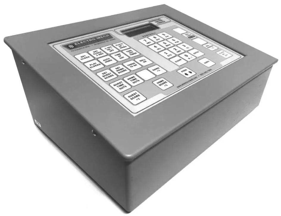
- Type
- FOOTBALL_1
- Options
- 00D0
- Version
- CXvF / CX_470_v1.HEX
The above information should match the label on the bottom of your control console.
The purpose of this manual is to explain how to use and maintain the Electro-Mech MP- Style control console for football scoreboard displays as well as for play clock accessory displays. The explanations and examples are based on the CX-Series controller hardware loaded with software version 4.7.0. Earlier versions of our hardware and software behave similarly, but not identically in all situations.
This combination of hardware and software is intended specifically to support Electro- Mech scoreboard models LX3120, LX3130, and LX3140. Additionally, this configuration is compatible with the following Electro-Mech models:
SEVEN WAYS TO STAY SAFE AND EXTEND CONTROLLER LIFE
1. Don't remove the grounding pin from the power cord. It's there to help keep you from getting shocked. If your receptacle only handles two-pronged power cords then your wiring was probably installed sometime before President Hoover left office. It's time to upgrade.
2. Keep your controller dry. We've designed our control consoles with outdoor activities in mind, but find some shelter if it is raining. The box is not waterproof. Drinks spilled over the keypad can lead to trouble too.
3. Unplug the power cable (and any data cables) when you are not using the controller. Noise over these cables ─ either from lightning, glitches in the power line, or some other accident ─ can damage the hardware. Leaving the control console connected 24-7 just increases the odds of bad things happening.
4. Store the controller in a clean, dry, secure area. Leave it where somebody can kick it, drop it, pile stuff on top of it, or steal it, and you can expect your controller will get kicked, dropped, piled on, and stolen. See also the "keep your controller dry" tip above. Neither sprinkler systems nor natural sources of precipitation are beneficial to your control console.
5. If you must open the enclosure, unplug the power cable (along with any data cables). Yes, it is possible to get shocked if you go poking around inside the control console.
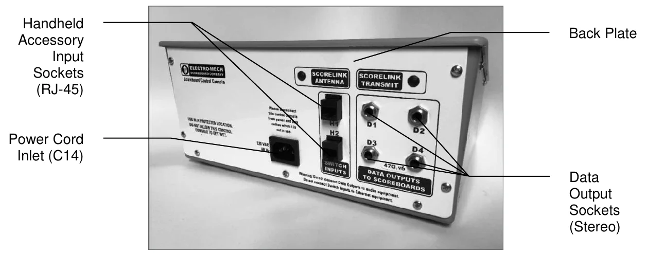
6. Don't plug something into the controller that doesn't belong there. Those stereo connectors in the back plate of the control console are the same kind used by audio equipment. The RJ-45 connectors for the handheld devices are the same type you often see in wired computer networks. Accidently plugging an audio amplifier or Ethernet access point into your scoreboard control console can cause problems ─ both to your controller and to your audio or networking equipment. A common mistake we see our customers make is to accidentally plug public address equipment into the junction box which leads to the scoreboard display. This is never healthy for components in the display.
7. Check out your equipment before game day. We're always happy to answer questions, walk you through solutions, repair damage, or sell replacement parts. But if your game starts in ten minutes, there is often not much we can do to help you. Make sure your scoreboard system is in good working order a few days before the game so that, however unlikely the chance of a problem, there will be time to solve it.
CONTROLLER PARTS AND ACCESSORIES
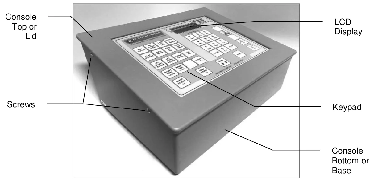
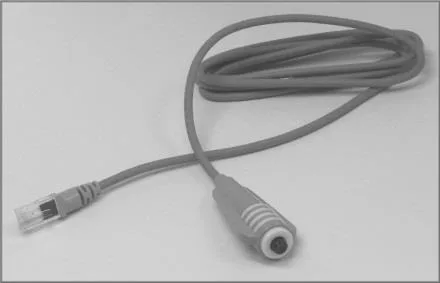
This is a generic set of photos identifying parts of the control console and accessories. You should receive a packing slip or other paperwork with your order that tells specifically what parts you are supposed to have. Your configuration may be different.
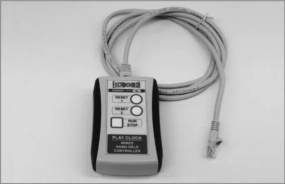
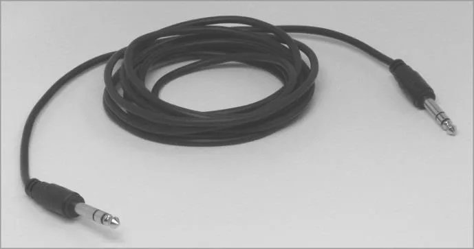
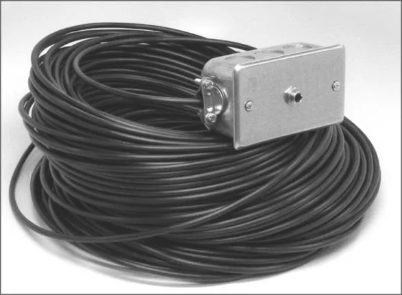
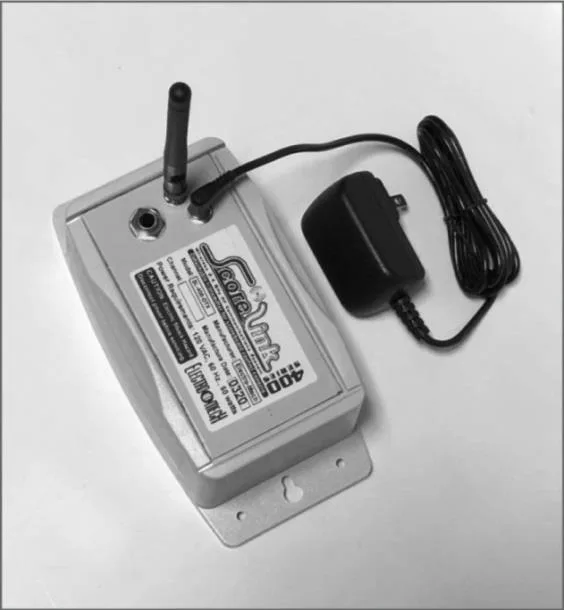
HOOKING UP AND POWERING UP THE CONTROLLER AND ACCESSORIES
1. Apply power to the scoreboard display(s).
2. Place the control console on a sturdy desk or table so that you have a clear view of the game's action as well as the controller's keypad and LCD display. You may hold the console in your lap, if you find it comfortable that way.
3. Attach handheld devices. You may have an external switch to start and stop the scoreboard's Main/Period Timer. You may also have a three-button device to operate Play Clocks. These corded switch assemblies plug into any RJ-45 style socket on the controller’s back plate. Your system may also include wireless handheld devices.
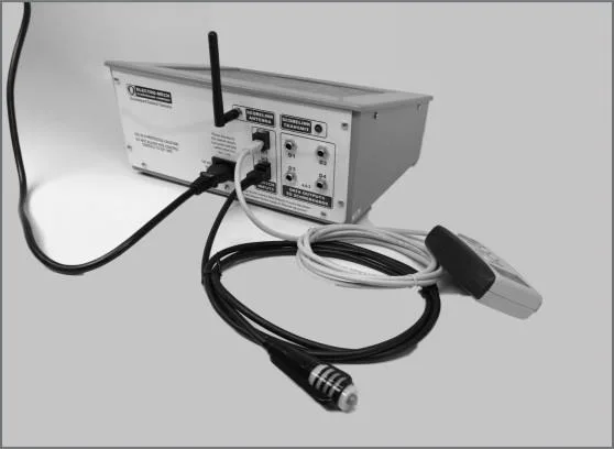
4. For installations using hardwired data cables, attach one end of your stereo patch cable to any available output connector on the back plate of the controller.
5. The next step for working with hardwired data is to attach the other end of the stereo patch cable to the junction box. If you have more than one scoreboard or optional display, each one will typically have its own junction box and its own stereo patch cable. If you have the ScoreLink wireless RF system, refer to the ScoreLink owner's manual for details.
6. Attach the power cord to the power inlet on the back of the control console, and plug the other end into a standard 120 VAC electrical outlet.
About one out of every few hundred customers asks us the question, "How do you turn the console on and off?" There is no power button on the controller. If it's plugged in, it's on. The logic here is that, for most installations, the scoreboard is not used very often. During the down time, the controller needs to be disconnected from the scoreboard display and from power to prevent damage from line noise and power surges. A power switch would discourage that good habit and provide a false sense of security.
Likewise, the scoreboard display should be disconnected from power when not in use. Therefore the controller has no means of turning the display on or off. However, a freshly powered on scoreboard display will show no information until it receives a good signal from the control console. So in order to "turn on" the scoreboard display, you have to power up and connect the control console.
CONTROL CONSOLE INITIALIZATION
Be quick. You only have about three seconds to see the splash screen when your controller powers up. It should look like this:
ELECTRO-MECH 470
FOOTBALL_1  00D0
The splash screen is telling you four things: The software author ─ ELECTRO-MECH The software version ─ 470 The selected scoreboard type ─ FOOTBALL_1 The selected option jumpers ─ D relates to how the Qtr. digit is addressed
This information is important for diagnostics, and you can get back to this splash screen by pressing [NEW GAME / OPTIONS] [1] [ENTER] on the keypad. If you see something different on your LCD display, either this is the wrong owner's manual for you or your controller is not configured to the expected standard.
If your control console has data from the previous game, you will be prompted to restore that data. Tap [1] [ENTER] to reload the old Scores and other information. Tap [0] [ENTER] to clear out memory and start over fresh. If you do not respond to this prompt, the controller will restore the previous game data automatically after a few seconds.
RESTORE GAME?
1=YES  0=NO  <1>
If your controller was previously in Practice Segment Timer mode, you will be prompted to restore the PST Program you were running when you powered off the console.
RESTORE PGM  01
1=YES  0=NO  <1>
This document will discuss the Practice Segment Timer Mode in detail a few pages later. For now, let's focus on how the controller behaves in Football Mode and assume you are starting with new data rather than restoring a game.
INITIALIZING IN FOOTBALL MODE
After the splash screen clears, the controller's LCD will show you the main stats it tracks during a Football game.
00  D12:00 1  00
  3  1 10 20   3
The scoreboard display will show the following information (some scoreboard models do not display all the functions listed):
- Left (Guest) Score
- 0
- Left (Guest) TOL
- 3
- Left (Guest) Possession
- blank
- Right (Home) Score
- 0
- Right (Home) TOL
- 3
- Right (Home) Possession
- blank
- Period/Game Time
- 12:00
- Period/Game Timer Direction
- D = Down-counting
- Quarter (Period)
- 1
- Down
- 1
- To Go
- 10
- Ball On
- 20
If you have Play Clocks connected to the control console, they will show 40 seconds.
CONTROL CONSOLE LCD SCREEN
During a Football Game, the LCD screen reflects the main stats rendered on the scoreboard display.
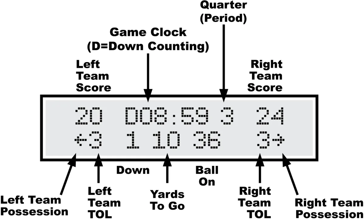
Numbers appearing as "0" on the LCD may show up as blanks on the scoreboard display. For instance, when the Down Count reads "0" on the control console, the digit on the scoreboard will be blank. Some scoreboard models do not include features like Time Outs Left and Possession Indicators, so, of course, the scoreboard will not match all the information on the LCD in those cases.
The illustration above refers to "Left Team" and "Right Team" to be as generic as possible. In most cases, the Left side is for the Guest team and the right side is for the Home team. Some scoreboard/controller pairs ship with the positions swapped.
KEY-BY-KEY OPERATION – BASKETBALL MODE
This section will provide a key-by-key explanation of the controller features. Use the [0] ... [9] buttons to respond to prompts, pressing [ENTER] to complete or confirm your response. The [CLEAR] button backs you out of a prompt (or skips to the next one) without making changes.
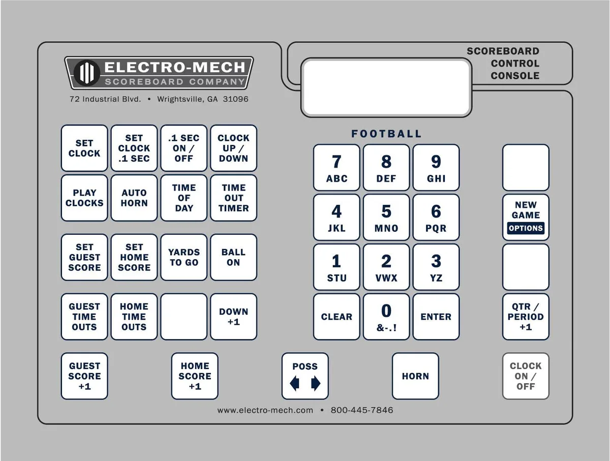
[SET CLOCK] - Available only when the Main (Period) Clock is NOT running. This button allows the operator to edit the time shown on the Main Clock. Tapping the button brings up an input prompt on the second line of the LCD screen.
SET CLK <15:00>
To set the time to 5:30, tap [SET CLOCK] [5] [3] [0] [ENTER]. The controller rejects time entries with a Seconds part greater than 59.
[SET CLOCK .1 SEC] - Available only when the Main (Period) Clock is NOT running and the Main Clock is in Down-Counting Mode with Tenth of Second Mode enabled. This button allows the operator to edit the time shown on the Main Clock, including the Tenth of Seconds digit, during the final minute of the Period. Tapping the button brings up an input prompt on the second line of the LCD screen.
SET SECS <00.0>
To set the time to 14.7 seconds, tap [SET CLOCK .1 SEC] [1] [4] [7] [ENTER]. The controller rejects entries greater than 59.9 Seconds.
[.1 SEC ON / OFF] - Available only when the Main (Period) Clock is NOT running and the Main Clock is in Down-Counting Mode. This button allows the operator to set the behavior of the Main Clock during the final minute of a Period. By default, during the final minute, the Clock shifts into Tenth of Second Mode, displaying Seconds in the area which usually shows Minutes, and Tenths of Seconds in the place where the Seconds Tens digit is otherwise seen. The operator may override this feature by disabling Tenth of Second Mode so that the Minutes and Seconds stay put and Tenths of Seconds are not displayed at all. Tapping the button brings up a two-line prompt on the LCD screen.
1/10TH SECOND
1=YES  0=NO  <1>
To turn off Tenth of Second Mode, tap [.1 SEC ON / OFF] [0] [ENTER]. To turn it back on, tap [.1 SEC ON / OFF] [1] [ENTER] or reset the controller via the New Game | Options menu.
[CLOCK UP / DOWN] - Available only when the Main (Period) Clock is NOT running. This button allows the operator to change the direction of the Main Clock. By default the Main Clock counts down until reaching 0:00. The operator may set the Main Clock to count up starting from any valid time. Pressing the button brings up a two-line prompt on the LCD display.
COUNT UP OR DOWN
1=UP 0=DOWN  <0>
To count up, press [CLOCK UP / DOWN] [1] [ENTER]. The Main Clock on the LCD display will show a "U" prefix to indicate Up-Counting Mode. A "D" is for Down- Counting Mode.
In Up-Counting Mode, the Hours part of the Clock is ignored, so after 99:59, the Main Clock cycles to 0:00 and continues counting.
[PLAY CLOCKS] - Allows the operator to edit the current display value and the programmable reset values associated with the Play Clock (Delay of Game) Timer. You must have Play Clock accessory displays and the three-button handheld switch assembly which ships with them for the function to be of any use.
As long as the Play Clock Timer is not running (actively counting down), tapping the [PLAY CLOCKS] button produces this prompt on the LCD:
CURRENT TIME<00>
To set the Play Clocks to show 12 Seconds, tap [PLAY CLOCKS] [1] [2] [ENTER]. You can tap [ENTER] at the CURRENT TIME prompt to skip to the next prompt without making changes. If the Play Clock Timer had been running when the operator tapped [SHOT CLOCKS], the controller would have bypassed the first prompt, leading us to the second one:
RESET 1 TIME<40>
This is where you program the first (top) button of the three-button handheld device. If you want that button to reset the Play Clock Timer to 60 seconds every time you press it, tap [6] [0] [ENTER] at this prompt. The "Reset 1" value also becomes the default time showing on a Play Clock display when you clear out old stat values via the "Scoreboard Reset" menu. You can tap [ENTER] to skip to the next prompt without making changes.
RESET 2 TIME<15>
This is where you program the second (middle) button of the three-button handheld device. If you want that button to reset the Play Clock Timer to 5 seconds every time you press it, tap [5] [ENTER] at this prompt. You can tap [ENTER] to accept the current value without making changes.
Any updates you make to the values associated with Reset 1 and Reset 2 will be saved by the control console and used as the default values in the future.
[AUTO HORN] - Allows the operator to set the behavior of the Main Horn at the scoreboard display. By default, the Main Horn is activated for about four seconds at the end of each Period. That is, when the Main (Period) Clock counts down to 0:00, the Horn sounds. You can turn off this feature by using the [AUTO HORN] button. Pressing it brings up this prompt:
AT END OF PERIOD
1=AUTO 0=OFF <1>
To turn off the Automatic Horn at the End of Period, press [0] [ENTER] at this prompt. You can tap [ENTER] to skip to the next prompt without making changes. Note that even with Auto Horn disabled, the operator can still activate the Main Horn manually using the [HORN] button.
The next prompt offers you control of the Main Horn at the end of a Time Out.
END OF TIME OUT
1=AUTO 0=OFF <0>
By default the Automatic Horn at the End of Time Out is disabled, but you can enable it by tapping [1] [ENTER] here.
[TIME OF DAY] - Available only when neither the Main (Period) Clock nor the Time Out Timer is running. This button allows the operator to use the scoreboard's Main Clock digits to show the time of day. Since accidentally sending the scoreboard into Time of Day Mode in the middle of a game could be confusing, the controller requires a confirmation before it will let the operator continue.
TIME OF DAY CLCK
1=YES  0=NO  <0>
Tap [1] [ENTER] to acknowledge that you want to use Time of Day Mode. The next prompt asks whether Scores, Quarter, and other features should remain illuminated on the scoreboard during Time of Day Mode or be blanked to indicate that a game is not underway.
 BLANK OTHERS?
1=YES  0=NO  <0>
Tap [1] [ENTER] to turn off the rest of the scoreboard display features.
Finally, you will be prompted to enter the current time of day (in 12-hour format).
SET CLK <12:05>
Tap [3] [4] [5] [ENTER] to set the Time of Day Clock to 3:45.
While the controller is in Time of Day Mode, the Clock digits on the LCD will have a "C" prefix. Most other buttons will work and update the values of their respective functions while the controller is in Time of Day Mode. For instance, you can still change the Total Points for each team. You can even change the value of the Main (Period) Clock using the [SET CLOCK] button, and your new value will be in place when you leave Time of Day Mode.
To exit Time of Day Mode, tap [TIME OF DAY] [0] [ENTER].
[TIME OUT TIMER] - Available only when the Main (Period) Clock is NOT running and the controller is not in Time of Day Mode. This button allows the operator to initiate a countdown of any duration less than ten minutes without losing track of the Main Clock information.
 TO SCOREBOARD?
1=YES  0=NO  <0>
The first prompt asks the operator if the Time Out Time should temporarily replace the Main (Period) Clock digits on the scoreboard display. Otherwise the countdown will be seen only on the controller's LCD. Tap [1] [ENTER] to show the Time Out Time on the scoreboard.
SET T-OUT <1:00>
At the second prompt, the operator should enter the duration of the Time Out (or whatever is being timed). To count down from Two Minutes, tap [2] [0] [0] [ENTER]. As soon as you tap [ENTER] the Time Out countdown begins. The Clock digits on the LCD will have a "T" prefix to indicate Time Out Timer Mode.
To stop the Time Out countdown, tap [TIME OUT TIMER] again. Pressing the [CLOCK ON / OFF] button while the Time Out Timer is running will abort the countdown and start the Main (Period) Clock running.
If the Auto Horn at End of Time Out feature has been enabled, the Main Horn will sound when the Time Out Timer reaches 0:00. The Time Out Timer is not affected by settings for Tenth of Second Mode (never shows Tenths) or Clock Direction (always counts down).
[SET GUEST SCORE] - Allows the operator to directly set or edit the Guest Team Total Points (a.k.a. Guest Score). Tapping the button brings up an input prompt on the second line of the LCD screen.
SET SCORE <00>
To set the Guest Team Total Points to 35, tap [SET GUEST SCORE] [3] [5] [ENTER].
Some scoreboard/console pairs ship with the positions of the Guest and Home keys swapped.
[SET HOME SCORE] - Allows the operator to directly set or edit the Home Team Total Points. Tapping the button brings up an input prompt on the second line of the LCD screen.
SET SCORE <000>
To set the Home Team Total Points to 120, tap [SET HOME SCORE] [1] [2] [0] [ENTER].
Some scoreboard/console pairs ship with the positions of the Guest and Home keys swapped.
[YARDS TO GO] - Allows the operator to set or edit the Yards To Go stat. Tapping the button brings up the following input prompt:
YARDS TO GO <10>
To set the Yards To Go to 15, tap [YARDS TO GO] [1] [5] [ENTER].
[BALL ON] - Allows the operator to set or edit the Ball On stat. Tapping the button brings up an input prompt on the second line of the LCD screen.
BALL ON <20>
To set Ball On to 29, tap [BALL ON] [2] [9] [ENTER].
[GUEST TIME OUTS] - Allows the operator to decrement the Guest Time Outs count by one.
[HOME TIME OUTS] - Allows the operator to decrement the Home Time Outs count by one.
[DOWN +1] - Allows the operator increment the Down count by one.
[GUEST SCORE +1] - Allows the operator to increment the Guest Team Total Points (a.k.a. Guest Scores) by one.
[HOME SCORE +1] - Allows the operator to increment the Home Team Total Points (a.k.a. Home Scores) by one.
[POSS | < >] - Toggles the Possession indicator between the Guest and Home sides. You can clear both Possession indicators by pressing and holding the [POSS | < >] button for about three seconds.
[HORN] - Sounds the Main Horn for a half-second burst.
[CLOCK ON / OFF] - Starts and stops the Main (Period) Clock.
[QTR. / PERIOD +1] - Allows the operator to increment the Period digit (in some cases referred to as the Quarters digit) by one.
[NEW GAME | OPTIONS] - Discussed on the pages which follow.
SUMMARY OF [NEW GAME / OPTIONS] FUNCTIONS
[0] = Exit [1] = Reset Sports Stats [2] = Brightness [3] = ScoreLink Group Selection (not typically available) [4] = Blank Test [5] = Lamp Test [6] = Practice Segment Timer blank select (PST Mode only) [7] = Electronic Team Names [8] = Precision Time Mode [9] = Practice Segment Timer Mode Long Press = Maintenance Sub-Menu
[0] = Exit [1] = Not Used [2] = Supply Voltage (for battery packs) [3] = PST Flags (partially supported) [4] = Radar Gun (not supported for this configuration) [5] = ScoreLink Signal Strength [6] = Not Used [7] = Not Used [8] = Not Used [9] = Not Used
PRACTICE SEGMENT TIMER MODE
The Practice Segment Timer (PST) mode of your football scoreboard controller is a powerful tool for creating, saving, editing, and running a set of programs, each defining the times which make up a practice schedule. You may have a simple practice schedule with two hours of practice broken into four 30-minute Segments, for instance. Or you may have a complicated practice schedule with several longer Segments interspersed with shorter Segments, break periods, one-minute drills, and more. A PST Schedule can include up to 90 Segments. You can create up to 45 of these PST Schedules (each containing 1 to 90 different Segments). That's over 4,000 individual Segments in all. You store these Schedules by assigning them a two-digit Schedule ID (a.k.a. Program ID). You may call up the PST Schedules to be run as many times as you like -- days, weeks, or years later.
Practice Segment Timer Mode can be used to control a general purpose scoreboard display, with the Segment Time showing in the Main (Period) Clock area and the Segment Count in the Home Score area. Or you may use your Play Clock displays as Practice Segment Timer displays. Or you may have purchased a special Practice Segment Timer display from Electro-Mech in one of several possible configurations. The multitude of options makes for a slightly complicated setup process. But, once you understand the questions the controllers ask you, it should make sense. The diagram below provides four examples of how your displays can be deployed to use the Practice Segment Timer Mode.
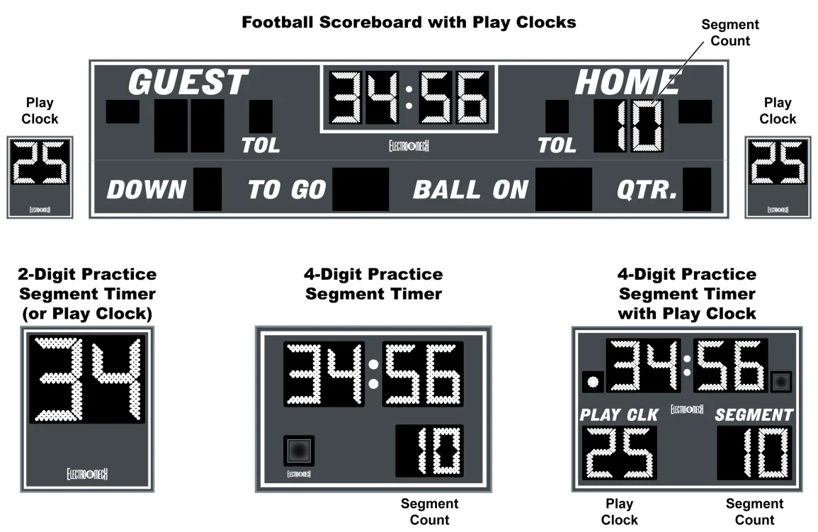
Practice Segment Timer Setup
From Football Mode, tap [NEW GAME | OPTIONS] [9] [1] [ENTER] to launch Practice Segment Timer Mode. The LCD will prompt you to enter a Program (Schedule) ID.
ENTER PROGRAM ID
NUMBER:     <01>
You can get to this same prompt from within Practice Segment Timer Mode by tapping [NEW GAME | OPTIONS] [9] [0] [ENTER].
This prompt is asking you to pick a two-digit number which you can use to refer to your collection of Segment Times. The number becomes your ticket to call up this Schedule over and over again in the future -- so you don't have to go through a setup process every time you have a practice. You could employ a different Program ID for each day of the week if your practice schedule varies by day. Or you could assign Program IDs to particular teams. If several people run practices using this controller, you can assign certain numbers to certain people. For instance, the athletic director might be allocated Program IDs 10 through 19; another coach might be assigned Program IDs 20 through 29. Pick whatever two-digit number is meaningful to you (up to 45).
If you select a Program ID which has already been associated with a Schedule, you will have the opportunity to completely overwrite that Schedule with new information or load the existing information.
OVERWRITE PROG?
1=YES  0=NO  <0>
Tap [0] [ENTER] if you want to load the Schedule, or tap [1] [ENTER] to begin fresh. This document will assume we are creating a new Program. Once you have created or loaded a Schedule, you can edit it by tapping [NEW GAME | OPTIONS] [9] and following the same steps described below.
The LCD will prompt you to enter the number of digits in your Practice Segment Timer Clock.
NUMBER OF DIGITS
IN CLOCK:    <4>
If you are using your football scoreboard as your Practice Segment Timer display, accept the default value of four digits by tapping [ENTER]. If you have a dedicated Practice Segment Timer display with a four-digit Clock, accept the default value by tapping [ENTER]. If want to use only your two-digit Play Clock displays as your Practice Timer, tap [2] [ENTER] here.
The next prompt can be a little confusing.
ENABLE PLAY CLK?
1=YES  0=NO  <0>
If you have a dedicated Practice Segment Timer displays with built-in digits for Play Clocks, you want to answer YES at this prompt. Also answer YES if you are using your main football scoreboard as your PST display. The tricky part is that when you are using your football scoreboard to show the Practice Segment Timer, you should answer YES whether or not you plan to use any Play Clock displays. YES tells the controller to send the Segment Count information to the address which happens to correspond to the Score digits on the right side of a football scoreboard (usually Home Scores). NO tells the controller to send that information to the address normally used by the Play Clocks. The only scenario where NO is the best answer is if you are using a dedicated Practice Segment Timer display which does NOT have Play Clock digits -- such as Electro-Mech model LX7520.
Next you will choose the total number of Segments in your Schedule.
**90 AVAILABLE**
TOTAL SEGS: <01>
For a Practice consisting of five timed periods, tap [5] [ENTER].
Now you enter the length of each Segment.
ENTER LENGTH OF
SEG #01  <00:00>
The length of a Segment cannot be 0 nor a time value with Seconds greater than 59. Any valid time from 1 Second to 99 Minutes 59 Seconds will work. Whether you're programming a two-digit or four-digit Clock, you are prompted for four digits here.
Let's assume your first Segment needs to be 12 Minutes 30 Seconds long. You tap [1] [2] [3] [0] [ENTER]. Now the LCD will prompt you to enter the length of the second Segment.
ENTER LENGTH OF
SEG #02  <12:30>
These prompts will continue until you have given a length of each Segment up to however many Segments you requested in the previous step. Notice that the default length for a given Segment is the same as the length of the previous Segment you entered, so you can just tap [ENTER] at these prompts if all your Segments are the same.
Next up: Clock Direction:
CLOCK DIRECTION
1=UP 0=DOWN  <0>
This is asking if you want to count time up from 0:00 or down to 0:00. Selecting an Up- Counting Timer disables the ability to show Tenths of Seconds on the Clock display -- which has the side effect of enabling the Flash Zone (see below) feature.
Tenth of Second Mode:
1/10TH SECOND
1=YES  0=NO  <1>
This prompt only shows up if you choose a four-digit Clock and select Down Counting at the previous prompt. Up-counting Timers never show Tenths of Seconds. For down- counting Timers, by default (that is, if you tap [ENTER] here) the Clock display will shift into Tenth of Second Mode for times less than one Minute. In this mode the Time is displayed as Seconds and Tenths (SS.t format) rather than Minutes and Seconds (MM:SS format). You can turn off this behavior by tapping [0] [ENTER] at the "1/10th Seconds" prompt.
If you are setting up a two-digit Practice Segment Timer or if you've disabled Tenth of Second Mode for your four-digit PST, you will next be prompted for the Flash Zone. You can ignore this prompt by tapping [ENTER].
 SET FLASH ZONE
(0=NONE) <00:00>
The Flash Zone feature allows you to make the Segment Time display blink on and off during the final portion of a Segment. The idea is to get viewers' attention when the Segment is about to end. So, if you tap [3] [0] [ENTER] at this prompt, you are saying that you want the Clock display to flash during the final 30 Seconds of each Segment. The Flash Zone feature works specifically for dedicated Practice Segment Timers and Play Clocks; it is not compatible with most scoreboards and will have no effect on the main scoreboard display.
Interval Time:
BETWEEN SEGMENTS
INTERVAL:<00:05>
This controls how long your PST Program pauses between each Segment. There are two reasons why you might want to change this value to 0. First, you may want the Timer to simply stop at the end of each Segment and wait for you to manually start it. Second, you may want to have absolutely no breaks between Segments. Setting it to 5 Seconds or more allows time for the Horn to die down between Segments. Or you could use the Interval Timer to allow a break of several minutes between Segments. Whatever value you choose, it will be the same in between all Segments. If you want to stop between Segments and manually restart the Clock, set this value to 0, and disable the Continuous Play feature (more on this later). Keep in mind that the Horn can be set to automatically sound at the end of each Segment but will never sound at the end of the Interval Time.
Display Interval:
DISPLAY INTERVAL
1=YES  0=NO  <0>
If you are programming for a four-digit Clock and you set you Interval Time to something other than 0 in the previous step, you'll be prompted to decide whether or not that Interval should be shown on the scoreboard display. The default is "No" -- meaning the Practice Segment Timer Clock will show 0:00 or 0.0 during the Interval (while the controller's LCD will count down the Interval time). If you respond [1] [ENTER] to this prompt, you are allowing the Interval Time to be displayed in same places the Segment Time is normally shown. If you have a two-digit Clock, this is not an option, so the controller skips the prompt.
Automatic End of Segment Horn Feature:
END OF SEG HORN
1=AUTO 0=OFF <1>
By default (that is, if you tap [ENTER] here) the Segment Timer Horn (and the Main Horn on the scoreboard) sounds at the end of each Segment. You may turn off this feature by tapping [0] [ENTER] at this prompt. If you have a dedicated Practice Segment Timer with a Visual Horn Indicator, the indicator will still illuminate at the end of the Segment no matter how you set the Segment Timer Horn to behave. You may still sound the Horn manually using the [HORN] button on the controller.
Segment Count Direction:
 SEGMENT COUNT?
1=UP 0=DOWN  <1>
By default the Segment Count starts at 1 and continues up to how ever many Segments you programmed. You may select down-counting mode by tapping [0] [ENTER] here.
Continuous Play Mode:
CONTINUOUS PLAY?
1=YES  0=NO  <1>
You'll see this prompt only if you had set the Interval Time to 0 a few prompts back. Continuous Play Mode means the Clock never stops (unless the operator manually stops it). Once Segment 1 is finished, Segment 2 automatically starts, etc. If you prefer to manually start the next Segment, tap [0] [ENTER] at this prompt. By the way, because it only makes sense to have an Interval Time if you want Continuous Play, you will always be in Continuous Play Mode if you set Interval Time to anything other than 0.
Continuous Loop Mode:
CONTINUOUS LOOP?
1=YES  0=NO  <0>
You'll see this prompt only if you've enabled Continuous Play Mode. If you tap [1] [ENTER] the Program will automatically start over at the end of the last Segment and continue from the beginning.
Practice Segment Timer Operation
Once you've created, loaded, or edited a Program (Schedule), your LCD will show something like this:
SEG 01     25:00
PROGRAM 35    40
"PROGRAM 35" tells you that you are currently using PST Schedule #35. Later, this area of the screen will provide other messages. The Segment Count is shown in the upper left part of the LCD. During an Interval Time you'll see the Next Segment displayed here. The lower right part of the LCD shows the Play Clock time, if you have enabled that feature. The upper right part shows the Segment Time (or Interval Time).
The following buttons on the control console are available for use when you are in Practice Segment Timer Mode:
[CLOCK ON / OFF] - This may be the only button you have to use once you've loaded your Schedule. Tap [CLOCK ON / OFF] to start the Segment Timer Clock. If you've enabled Continuous Play Mode, the Clock will continue to run until all your Segments have been completed.
Once you start the Clock running, only two buttons on the keypad have any effect. You can either use [CLOCK ON / OFF] to stop the Clock or use [HORN] to sound the Segment Timer Horn.
[HORN] - Sounds the Segment Timer Horn (and the Main Horn on the Scoreboard, if the controller is attached to a scoreboard display) for a one-second burst.
[QTR. / PERIOD +1] - Available only when the Segment Clock is NOT running. This button advances to the beginning of the next Segment. If you are currently showing the last Segment of a Schedule, tapping [QTR / PERIOD] will cycle you back to the first one.
[CLEAR] - Available only when the Segment Clock is NOT running. This button allows you to reset the current Segment back to its starting time. If you tap [CLEAR] at the beginning of a Segment, you'll go to the start of the previous Segment.
[SET CLOCK] - Available only when the Segment Clock is NOT running. This button allows the operator to edit the time shown on the Segment Clock. Tapping the button brings up an input prompt on the second line of the LCD screen.
SET CLK <15:00>
To set the time to 5:30, tap [SET CLOCK] [5] [3] [0] [ENTER]. The controller rejects time entries with a Seconds part greater than 59. Any changes you make to the Time will last only until the end of the current Segment or Interval. Afterwards, all times revert to their programmed values.
[SET CLOCK .1 SEC] - Available only when the Segment Clock is NOT running. The button is disabled for two-digit Practice Segment Timer Programs or Programs using an up-counting Timer. It allows the operator to edit the time shown on the Segment Clock during the last minute of a Segment -- including the Tenth of Seconds digit. Tapping the button brings up an input prompt on the second line of the LCD screen.
SET SECS <00.0>
To set the time to 14.7 seconds, tap [SET CLOCK .1 SEC] [1] [4] [7] [ENTER]. The controller rejects entries greater than 59.9 Seconds. Any changes you make to the Time will last only until the end of the current Segment. Afterwards, all times revert to their programmed values.
[.1 SEC ON / OFF] - Available only when the Segment Clock is NOT running. The button is disabled for up-counting Segment Clocks. It is also disabled for two-digit Practice Segment Timer Programs.
This button allows the operator to set the behavior of the Clock during the final minute of a Segment. By default, during the final minute, the Segment Clock shifts into Tenth of Second Mode, showing Seconds in the area that usually shows Minutes and Tenths of Seconds in the place where the Seconds Tens digit is otherwise seen. The operator may override this feature by disabling Tenth of Second Mode so that the Minutes and Seconds stay put and Tenths of Seconds are not displayed at all. Tapping the button brings up a two-line prompt on the LCD screen.
 1/10TH SECOND
1=YES  0=NO  <1>
To turn off Tenth of Second Mode, tap [.1 SEC ON / OFF] [0] [ENTER]. To turn it back on, tap [.1 SEC ON / OFF] [1] [ENTER]. Any changes you make to Tenth of Second Mode will last only as long as you continue to run the currently loaded Program (Schedule). If you reload the Program or load a new one, the Tenth of Second Mode will revert to the programmed value.
If you created a Practice Segment Timer Program with a four-digit Clock and you disabled Tenth of Second Mode during setup, you may have enabled Flash Zone. If you then use the [.1 SEC ON / OFF] button to enable Tenth of Second Mode, Flash zone will be disabled. The two features are mutually exclusive.
[AUTO HORN] - Allows the operator to set the behavior of the Segment Timer Horn. By default, the Horn attached to the scoreboard/PST diaplay is activated for about two seconds at the end of each Segment. That is, when the Clock counts down to 0:00, the Horn sounds. You can turn off this feature by using the [AUTO HORN] button. Tapping it brings up this prompt:
END OF SEG HORN
1=AUTO 0=OFF <1>
To turn off the Automatic Horn at the End of each Segment, tap [0] [ENTER] at this prompt. You can tap [ENTER] to skip to the next prompt without making changes. The next prompt offers you control of the Horn at the end of a Time Out.
END OF TIME OUT
1=AUTO 0=OFF <0>
By default the Automatic Horn at the End of Time Out is disabled, but you can enable it by tapping [1] [ENTER] here.
[TIME OF DAY] - Available only when the Clock is NOT running; disabled for two-digit Practice Segment Timer Clocks. This button allows the operator to use the scoreboard or Practice Segment Timer to show the time of day.
TIME OF DAY CLCK
1=YES  0=NO  <0>
Tap [1] [ENTER] to continue.
At the next prompt, enter the current time. The LCD will remind you that the controller is in Time of Day Mode:
     11:35
TIME OF DAY MODE
To exit Time of Day Mode, press [TIME OF DAY] [0] [ENTER].
[TIME OUT TIMER] - Available only when the Clock is NOT running and the controller is not in Time of Day Mode; disabled for two-digit Practice Segment Timer Clocks. This button allows the operator to initiate a countdown of any duration less than ten minutes without losing track of the Segment Time information.
 TO SCOREBOARD?
1=YES  0=NO  <0>
The first prompt asks the operator if the Time Out Time should temporarily replace the Clock digits on the scoreboard/PST display. Otherwise the countdown will be seen only on the controller's LCD. Tap [1] [ENTER] to show the Time Out Time on the scoreboard.
SET T-OUT <1:00>
At the second prompt, the operator should enter the duration of the Time Out (or whatever is being timed). To count down from Two Minutes, tap [2] [0] [0] [ENTER]. As soon as you tap [ENTER] the Time Out Countdown begins.
To stop the Time Out Countdown, tap [TIME OUT TIMER] again.
If the Auto Horn at End of Time Out feature has been turned on, the Horn will sound when the Time Out Timer reaches 0:00. The Time Out Timer is not affected by settings for Tenth of Second Mode (never shows Tenths) or Clock Direction (always counts down). Tapping the [CLOCK ON / OFF] button while the Time Out Timer is running will abort the countdown and start the Segment Clock running.
[NEW GAME | OPTIONS] - Available only when the Clock is NOT running. As it does
in Football Mode, in PST Mode this button serves as a gateway to several menu
functions including...
- [NEW GAME | OPTIONS] [1] [ENTER] = reset stats (returning to Football Mode).
- [NEW GAME | OPTIONS] [4] = blank test.
- [NEW GAME | OPTIONS] [5] = lamp test.
In addition, the New Game | Options menu includes special features available in Practice Segment Timer Mode.
[NEW GAME | OPTIONS] [6] - Available only when the Clock is NOT running. This feature allows the operator to hide either the Clock or the Segment Count or both. The first time you press [NEW GAME | OPTIONS] [6], the LCD will show you what is about to happen:
 HIDE CLOCK
SHOW SEGMENT
Press [ENTER] to continue, and the Clock digits on the scoreboard display will go blank. You will continue to see the Clock on the controller's LCD screen. Tap [NEW GAME | OPTIONS] [6] [ENTER] again to restore the Clock and hide the Segment Count. Press these keys again to hide both, and a fourth time to turn both back on. You can quickly cycle through the various combinations by pressing [NEW GAME | OPTIONS] [6], then press [6] repeatedly until the LCD indicates the condition you are looking for. Press [ENTER] to accept that condition and complete the command.
The feature will not be available if you are using a Schedule created for a two-digit Clock.
[NEW GAME | OPTIONS] [9] - Available only when the Clock is NOT running. This feature allows you to edit your current Program or load or create a new Program.
EDIT PROGRAM 36?
1=YES  0=NO  <0>
If you press [1] [ENTER] at this prompt, you will be taken through the same series of prompts that you saw when you set up the Schedule the first time. This time through, all the default values will be filled in with old values from your Program. You can quickly cycle through your original Program values by pressing [ENTER] repeatedly until you reach a value that you want to change.
If you answer [0] [ENTER] to the "EDIT PROGRAM" prompt, you will be given a chance to enter a new Program ID. Here you may load an existing Program or start a new one.
WIRED HANDHELD CLOCK START-STOP SWITCH
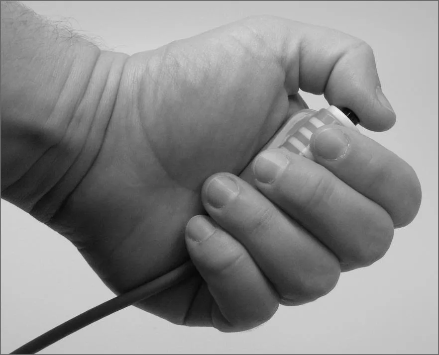
Some of our football scoreboard packages ship with a handheld pendant-style switch which plugs into the back of the control console and gives a separate operator the ability to start and stop the Main (Period) Clock (or the Segment Timer Clock). The RJ- 45 style connector at one end of the handheld unit's cable can plug into either one of the console sockets labeled "H1" or "H2" in the "SWITCH INPUTS" area. On older control consoles, these sockets are labeled "CLOCK Hand-held" and "DGT / SC Hand-held". The pendant end fits nicely in your hand so that your thumb rests on the switch. Press the switch once to start the Clock. Press the switch again to stop the Clock.
Wired Handheld Three-Button Switch Assembly for Play Clocks
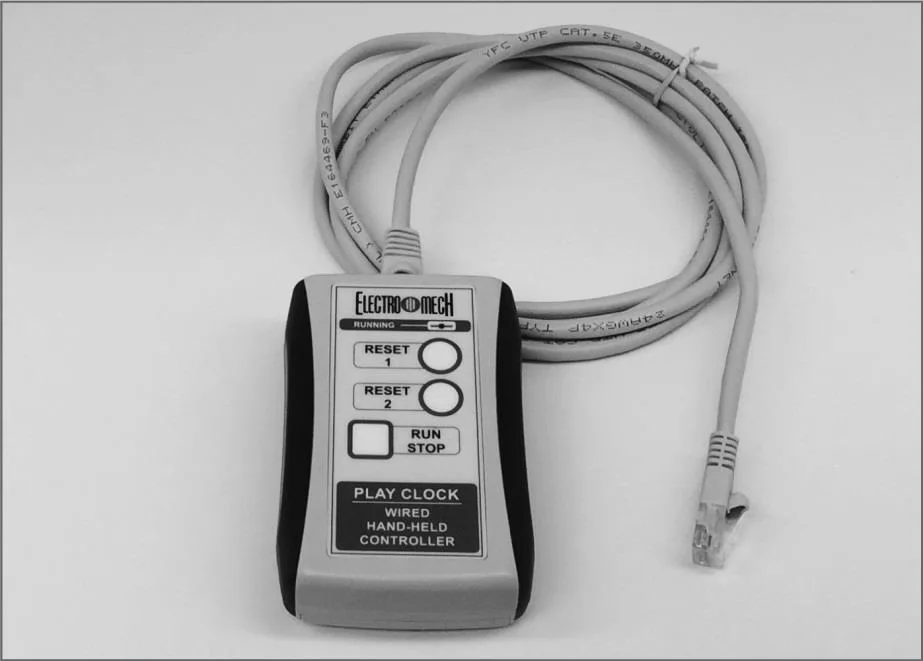
If you purchased a set of Play Clocks, your package includes a handheld three-button switch assembly. The RJ-45 style connector at one end of the handheld unit's cable can plug into either one of the console sockets labeled "H1" or "H2" in the "SWITCH INPUTS" area. Here's what the buttons do:
Top Button = Set the Play Clocks to Reset 1 value (default = 40 seconds).
Middle Button = Set the Play Clocks to Reset 2 value (default = 25 seconds).
Bottom Button = Start / Stop the Play Clock Timer.
Using the [PLAY CLOCKS] button on the main control console, you may assign any number, from 1 to 99 seconds, to Reset 1 and Reset 2. Unlike most other settings, these reset values are "sticky" through a [NEW GAME] [1] clearing of the game data.
CONTROL CONSOLE POWER DOWN AND STORAGE
There is no "OFF" switch on the control console; nor is there a function on the controller which turns the scoreboard display(s) off. The scoreboard system should be disconnected from power when not in use. Electro-Mech recommends installing a disconnect switch for all permanently mounted scoreboard displays. You may simply unplug a portable scoreboard display and store it between games.
You should unplug your control console both from its power receptacle and from its data cable (if present) when you are not using it. Electro-Mech offers a carrying case which provides a convenient way to store and transport the controller along with various cables and other accessories. Whether you have a case or not, you should store the control console in a safe, dry location between games.
If the controller loses connection with the scoreboard display while the sign is powered, the scoreboard display will freeze up ─ showing the last good Time, Score, and other information it received from the controller. The scoreboard display will synchronize with the control console again as soon as you reestablish the connection.
If the scoreboard display loses power with the control console still connected and powered, nothing will happen other than the scoreboard display going blank. Again, the display will synchronize with the controller as soon as it receives power.
If the control console loses power ─ either because you intentionally unplug it or because of something unexpected ─ it will save the current game information to its permanent local memory. When you next apply power to the controller, the LCD will prompt you to restore the previous game or Practice Segment Timer Program. If you fail to respond to the prompt, the game data will restore automatically after a few seconds.
JUMPER SETTINGS
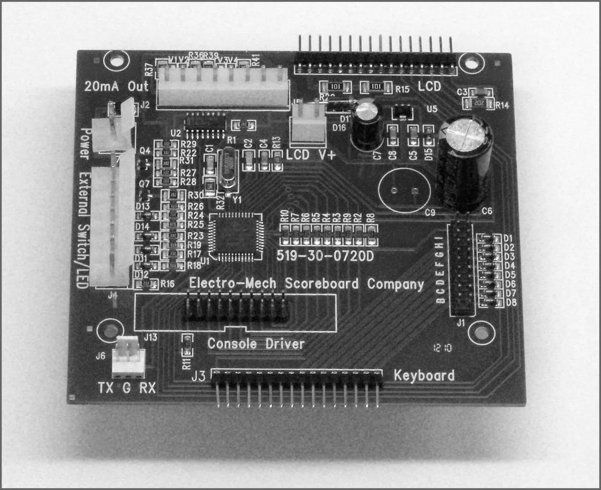
*** Important: If you plan to open up the control console and do work inside the box, make sure the power cable is disconnected from the receptacle! ***
The PCB that is the heart of the CX controller is called the CX driver. This driver contains a set of jumper pins that can be used to tell the software how to behave. By installing shunts across a pair of pins, you are, in essence, closing a switch that tells the program to do something. On some CX drivers these pins are labeled B through I, A through I, or A through J. On other drivers the A, B, C,... labels are missing, but you will find a corresponding diode next to pins B through I (A and J are not for jumpers). The diodes are labeled D8 through D1 (D8 = B, D7 = C, etc.).
Jumper pins A and J are used for attaching a programming cable to the CX driver and don't really do anything in this context. Pins F, G, H, and I are the "Sport Type Jumpers" which determine the sport. So, for instance, by adding a shunt across the "I" pins, you can make your controller think that it is operating an Electro-Mech basketball scoreboard rather than a football display. This table summarizes the jumper settings for the Board Type Jumpers:
| Board Type | F | G | H | I | Models / Comments |
|---|---|---|---|---|---|
| BASEBALL_3 | LX10xx, LX12x0, LX134x | ||||
| BASEBALL_4 | X | LX1360 | |||
| FOOTBALL_4 | X | LX1360, LX31xx | |||
| BASEBALL_1 | X | X | LX10xx, LX11xx, LX12xx, LX134x | ||
| BASEBALL_2 | X | Not supported in this software | |||
| SOCCER_LX | X | X | Not supported in this software | ||
| SOCCER | X | X | Not supported in this software | ||
| HOCKEY | X | X | X | Not supported in this software | |
| LINESCORE4 | X | Not supported in this software | |||
| LINESCORE5 | X | X | LX14xx, LX16xx, LX17xx | ||
| FOOTBALL_1 | X | X | LX3xxx, LX7520, LX76x0 | ||
| BASKETBALL | X | X | X | LX2xxx (except Player Stats), 72xx | |
| MP-14X | X | X | Not supported in this software | ||
| MP-15X | X | X | X | Not supported in this software | |
| MULTISPORT | X | X | X | LX1320, LX137x, LX1390, LX3450, LX6324 | |
| HOCKEY_LX | X | X | X | X | Not supported in this software |
Pins B, C, D, and E are the "Option Jumpers." Each one typically controls one of four options for a given Sport Type. This document discusses the options for the Football Sport Type only. You'll have to look at the Owner's Manual for consoles configured for the other Sport Types if you are curious about their Option Jumpers.
Jumper B = 5 Time Outs (Install this jumper to have 5 Time Outs Left instead of 3) Jumper C = 9 Time Outs (Install this jumper to have 9 Time Outs Left instead of 3) Jumper D = Period/YTG swap (remove to handle LX3150 Yds. To Go addressing) Jumper E = 5-Digit Clock (Install this jumper if your scoreboard has a 5-digit Timer)