
Home / Documentation / Owner's manual
Download the original PDF (818 kB)
This page reproduces the text of the PDF above without alteration, so the document can be read, searched and linked to directly.

MP-386 SOCCER SCOREBOARD
OWNER’S HANDBOOK
Thank you for choosing an Electro-Mech Scoreboard for your athletic complex. We are confident that your new scoreboard will give many years of reliable service.
Rev. 3 Revised: 08/02/02
MP-386 SCOREBOARD SPECIFICATIONS
GENERAL: This ETL listed scoreboard includes the scoreboard cabinet, mounting hardware, control console, 10 ft. extension cable, and junction box.
DIMENSIONS: MP-386:20’ L x 8’ H x 6” D (MP-386 with a side sponsor panel measures 28’ L x 8’ H x 6” D)
WEIGHT: MP-386: ? lbs (MP-386 with a side sponsor panel weighs ? lbs) (MP-386 with two side sponsor panels weigh ? lbs)
SCOREBOARD CONSTRUCTION: The scoreboard consists of two sections. The outer frame is made from extruded aluminum. Internal structural parts may be extruded aluminum or formed from aluminum sheet. The face and back are made from aluminum sheet. The face and expanded metal screens are finished with enamel paint. Black is the standard color. Captions are white. The optional side sponsor panel is made in a separate extruded aluminum frame.
DISPLAY: The MP-386 soccer scoreboard displays HOME and VISITOR scores, shots on goal (SHOTS), and corner kicks (C KICKS) to 99, TIME to 99 minutes and 59 seconds (99:59), and PERIOD to 4.
LAMP BANKS: A 4 x 7 matrix of lamps forms each digit. The HOME score, VISITOR score, and TIME digits are 24” tall. The SHOTS, C KICKS, and PERIOD digits are 18” tall. The scoreboard uses 15 watt 120 VAC frosted medium based appliance lamps (also known as 15A15IF lamps). Recessed aluminum reflectors provide a crisp separation between each lamp. Expanded metal screens protect the lamps.
POWER REQUIREMENTS: Scoreboard - 120 VAC, 42.5 A, 60 Hz, 5100 watts maximum, (60 A service recommended). The scoreboard may be connected to either 120 VAC or 240 VAC single phase. Control Console - 120 VAC, 0.5 A, 60 Hz
SCOREBOARD ELECTRONICS: 100% solid state fully enclosed within 4 plug in modules.
CONTROL CONSOLE: The control console features a microprocessor, 37 key sealed membrane keypad, a LCD display, an attached 6 foot power cord, and either a lithium cell battery or two super capacitors to retain game information. The console housing consists of ABS plastic base and top pieces with a steel back plate.
CONTROL CABLE: The cable has two 22 AWG stranded copper conductors with semi-rigid PVC insulation. It also has a braided shield and a foil shield. The polyethylene jacket is rated at 300 volts. The cable is direct burial rated and measures approximately ¼” in diameter. This item is sold separately from the scoreboard.
JUNCTION BOX AND EXTENSION CABLE: A 4 ¼” x 2 ¼” x 2” junction box with a ¼” stereo jack mounted on the face plate is attached to the control cable at the point of operation. A 10 ft. extension cable connects the control console to the junction box.
SCORELINK 300 RF MODEM SYSTEM: This accessory can be used in place of control cable and junction box for this scoreboard without internal modifications to the scoreboard or the control console. Refer to the SCORELINK 300 RF MODEM SYSTEM OWNER’S HANDBOOK for more information.
WARRANTY: Five year limited warranty.
SCOREBOARD INSTALLATION
This part of the manual describes the mechanical and electrical installation of the scoreboard.
One of the items listed below must be purchased in order to complete the installation:
- Control cable (length dependent upon installation site layout)
- ScoreLink 300 RF Modem System
Items not provided by Electro-Mech Scoreboard Company that are necessary for
installation:
- Two posts (Three posts for MP-386 with optional side sponsor panel)
- Power cable to connect the scoreboard to the power source
- Grounding hardware
- A grounded NEMA 5-15R 120 VAC receptacle for the control console at the
scorekeeper’s table.
Items not provided that are recommended by Electro-Mech Scoreboard Company for
installation:
- A weatherproof power disconnect at the scoreboard
- A weatherproof NEMA 5-15R 120 VAC convenience receptacle at the
scoreboard.
Electro-Mech Scoreboard Company performs installations in some areas. In other areas, we can help you contact an independent installer. In areas in which installation service is not available from Electro-Mech Scoreboard Company, we will make every effort to answer your installation questions. Qualified personnel should perform the scoreboard installation. Consult national and local codes before installation.
MECHANICAL INSTALLATION
The mechanical installation includes installing the posts and mounting the scoreboard and the optional side or top sponsor panels (if purchased) to the posts.
Post Installation The scoreboard mounts on two posts (three posts for MP-386 with optional side sponsor panel). Typically installers will use steel pipes or I-beams. In order to reduce the glare from the sun on the front of the scoreboard, position the posts so that the front of the scoreboard is angled away from the afternoon sun, if possible. The mounting hardware will accommodate posts up to 7 inches outer diameter. Sink the posts in reinforced concrete footings. Figure 1 shows the spacing of the posts for a MP-386 scoreboard. The specifications for the posts and concrete footings are dependent upon the expected local wind and soil conditions, the height of the scoreboard from the ground, and the local building codes. Electro-Mech Scoreboard Company assumes no responsibility for the installation of scoreboards by others.
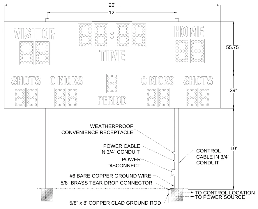
Figure 2 shows the spacing of the posts for a MP-386 with an optional side sponsor panel. The side sponsor panel is a separate assembly that bolts to the side of the scoreboard.
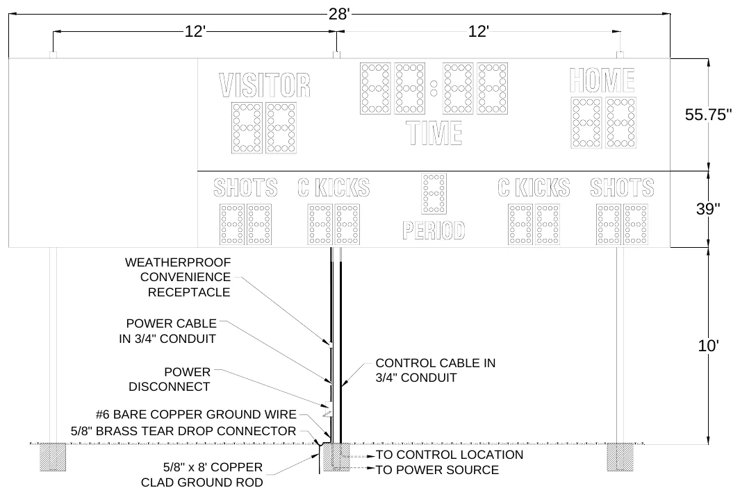
Figure 3 shows the spacing of the posts for a MP-386 with two optional side sponsor panels. The side sponsor panels are separate assemblies that bolt to the sides of the scoreboard.
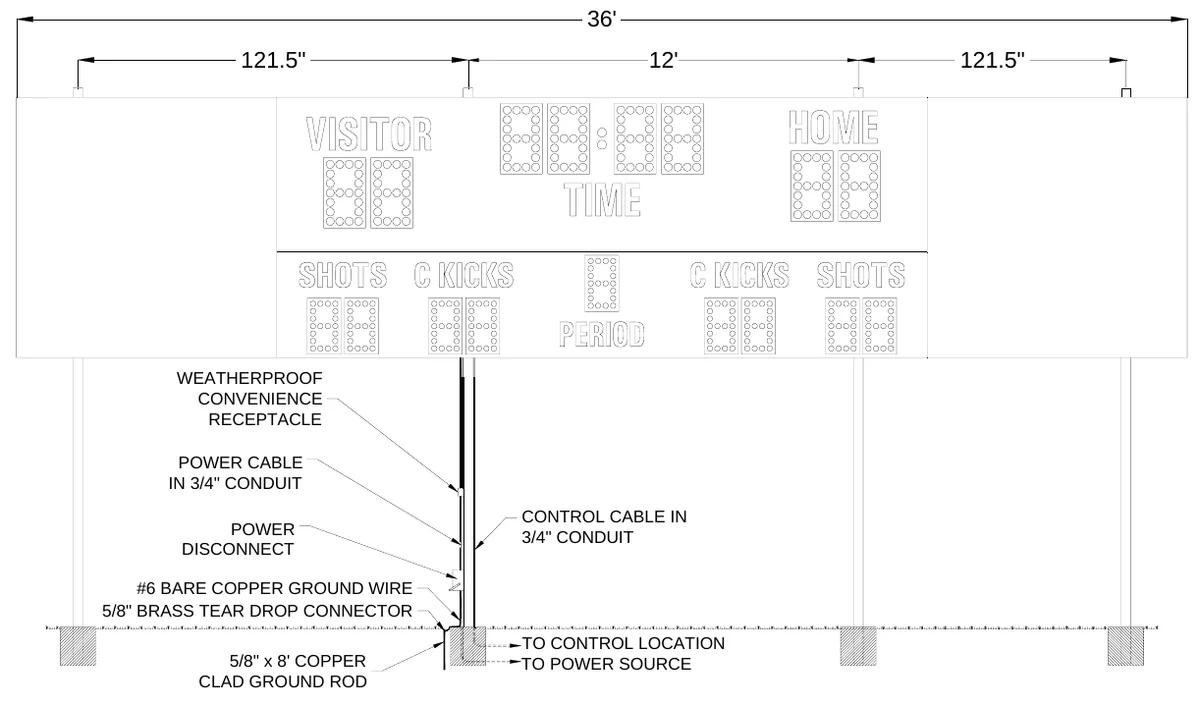
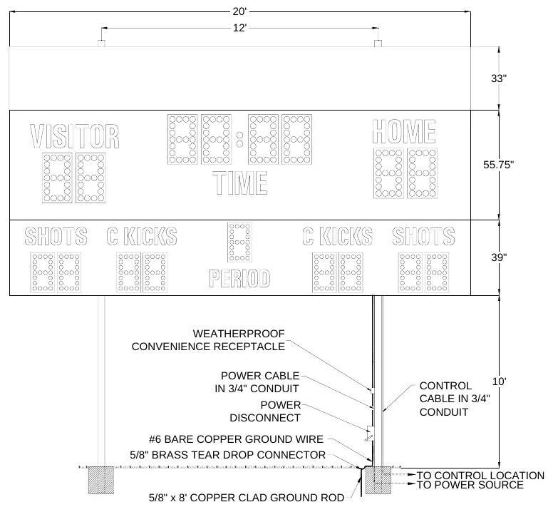
Figure 4 shows the spacing of the posts for a MP-386 with an optional top sponsor panel. This panel is a separate unit that mounts on the same posts as the scoreboard.
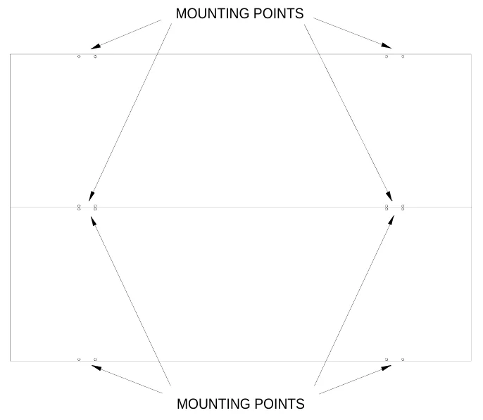
Mounting The Scoreboard The scoreboard is attached to the posts at eight points. Figure 5 shows the location of the mounting points on the rear of the scoreboard.
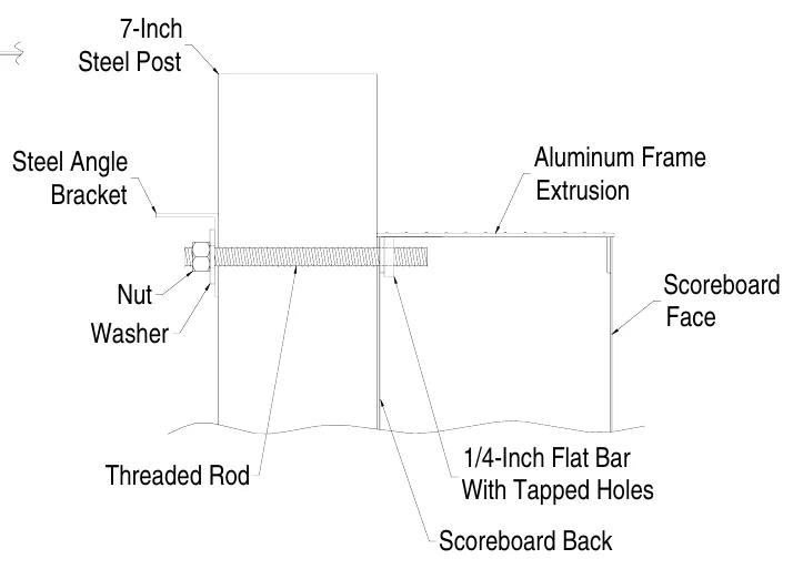
Eight sets of mounting hardware are provided to attach the scoreboard to the posts. Additional hardware sets are provided to attach the optional sponsor panels, if ordered. A mounting hardware set consists of a steel angle bracket, two threaded rods, two washers, and two nuts. Figure 6 shows an overhead cross section view and a side cross section view of the scoreboard attached to a post at a mounting point using the hardware. A ¼” flat bar with tapped holes is riveted to the inside of the scoreboard’s aluminum extrusion frame. The threaded rods screw into these tapped holes. The washers and nuts are used to clamp the steel angle bracket against the steel post and hold the scoreboard in place.
| Overhead Cross Section View | Side Cross Section View | ||||||
|---|---|---|---|---|---|---|---|
| 1/4-Inch Flat Bar | |||||||
| With Tapped Holes | 7-Inch Steel Post | ||||||
| Extrusion Lip | 7-Inch | ||||||
| Scoreboard | Steel Post | ||||||
| Back | |||||||
| Threaded Rod | Steel Angle | Aluminum Frame | |||||
| Steel Angle | Bracket | Extrusion | |||||
| Bracket | |||||||
| Nut | Scoreboard | ||||||
| Nut Washer | Face | ||||||
| Washer |
The following steps describe how to mount the scoreboard on the posts: 1.Place the lower section of the scoreboard against the posts on the ground. Make sure the mounting points are aligned with the posts. 2.If the eyebolts are installed in the upper section of the scoreboard, unscrew them and screw them into the lower section of the scoreboard. 3.Screw the threaded rods into the tapped holes in the scoreboard. 4.Place an aluminum angle bracket over the threaded rods at a mounting point. 5.Place a washer over each threaded rod. 6.Screw the nuts onto the threaded rods so that the bracket is loosely held in place. 7.Repeat steps 4 -6 at the other mounting points. 8.Raise the section into place and tighten the nuts to clamp it in place on the posts. 9.Unscrew the eyebolts from the lower section of the scoreboard and screw them into the upper section of the scoreboard. 10.Place the upper section of the scoreboard against the posts a few inches above the lower scoreboard section. Make sure the mounting points are aligned with the posts.
11.There is a cable with a 15 pin plug which is accessible through an opening in the top of the lower section frame. Plug this cable into the 15 pin socket which is accessible through an opening in the bottom of the top section frame. 12.Place the upper section of the scoreboard on top of the lower section. 13.Attach the mounting hardware by the same method as the lower section. 14.Tighten the nuts to clamp it in place on the posts.
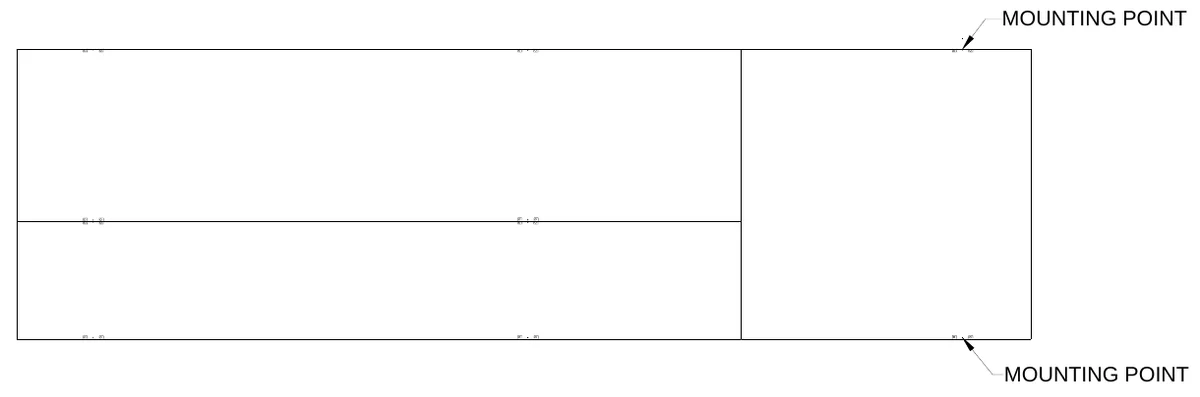
Mounting The Optional Side Sponsor Panel If you purchased the optional side sponsor panel, the scoreboard has been modified so that the sponsor panel bolts to the side of the scoreboard cabinet. 1.There are several small access panels on the rear of the scoreboard and side sponsor panel. Remove these access panels. 2.Use the provided hardware to bolt the sponsor panel to the scoreboard. 3.Re-install these access panels. 4.Clamp the sponsor panel to the scoreboard post at the two mounting points using the same type of hardware used on the scoreboard sections. Figure 7 shows the mounting points for the optional side sponsor panel.
Mounting The Optional Top Sponsor Panel Additional hardware sets are provided to attach the optional top sponsor panels, if purchased. The following steps describe how to mount the top sponsor panel on the posts:
1.Raise the sponsor panel in place above the scoreboard. Make sure the mounting points are aligned with the posts. 2.Screw the threaded rods into the tapped holes in the top sponsor panel.
3. 4. 5. 6. 7.
Place a steel angle bracket over the threaded rods at a mounting point. Place a washer over each threaded rod. Screw the nuts onto the threaded rods so that the bracket is loosely held in place. Repeat steps 4 -6 at the other mounting points. Tighten the nuts to clamp it in place on the posts.
ELECTRICAL INSTALLATION
We recommend a qualified electrician perform the needed electrical connections to ensure proper operation of the scoreboard. These connections include grounding the scoreboard, connecting the scoreboard to a power source, installing the horn, installing the ScoreLink 300 or the control cable, and connecting the control console.
Ground Connection The National Electrical Code requires a scoreboard (electric sign) to be grounded. Grounding the scoreboard helps the scoreboard electronics operate properly and helps minimize damage if it is struck by lightning. Metal posts do not provide an adequate ground path. The following steps describe how to connect the scoreboard to the power source:
1.Drive one or more 5/8” x 8’ copper clad ground rods in the soil near the scoreboard. 2.Connect #6 bare copper wire to the ground rods using 5/8” brass tear drop connectors. 3.Attach the ground conductor to the each section of the scoreboard with copper mechanical lugs. Fasten the mechanical lugs to the scoreboard using self tapping sheet metal screws.
Power Connections The scoreboard may be connected to 240 VAC single phase or 120 VAC service at the scoreboard. Maximum power consumption of Model MP-386: 5100 Watts. Make sure that power cable is rated for this electrical load. Install the power cable in conduit. Avoid running the power cable in close proximity to the control cable. The following steps describe how to connect the scoreboard to the power source:
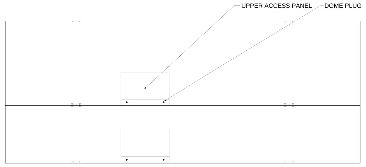
1.Remove the rear access panel of the upper scoreboard section and the dome plugs on the plate below the access panel. Figure 8 shows the location of the upper rear access panel and the dome plugs.
2.Figure 9 shows the view behind the access panel. Feed the power cables through one of the holes in the plate below the access panel. 3.Crimp fork terminals to the power cable wires.
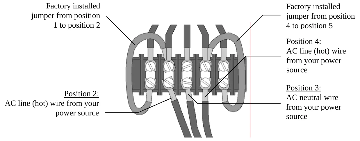
4.If you are going to connect the scoreboard to a 240 VAC supply, connect one AC line wire to position 2, AC neutral wire to position 3, and the other AC line wire to position 4 of terminal strip T4 on the junction chassis according to figure 10.
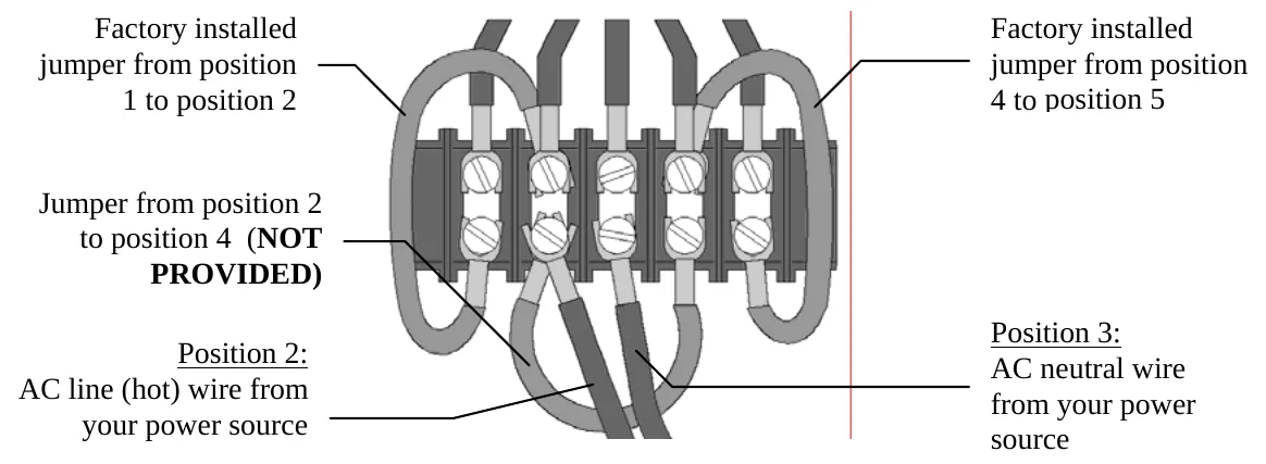
5.If you are going to connect the scoreboard to a 120 VAC supply, connect the AC line wire to position 2 and the AC neutral wire to position 3 of terminal strip T4 on the junction chassis. Add a jumper from position 2 to position 4. This jumper is not provided. Refer to figure 11.
Install a power disconnect that isolates all current carrying conductors on one of the posts below the scoreboard (not the ground conductor). If a secondary switch is installed near the scorekeeper’s table, it should also isolate these conductors. Place the power disconnect in the OFF position between games to help protect the scoreboard from lightning damage. A power disconnect on the scoreboard post also provides a convenient way of turning the scoreboard off during maintenance or repairs.
Horn Installation The items provided to install the horn are the horn, the weatherproof back box, the mounting bolt, and the mounting bracket. Items which are not provided but are necessary for proper installation are ¾” flexible conduit, a ¾” right angle male conduit connector, a ¾” straight male conduit connector, two wires, and four forked crimp terminals. The electrical requirements for the horn are 0.35 A 120 VAC. The horn is normally mounted to the top of the MP-386. The horn may be mounted on the side if the scoreboard has a top sponsor panel. A tapped hole is provided to fasten the horn to the scoreboard. The mounting bolt is screwed into the tapped hole at the factory. The following steps describe the assembly and mounting of the horn:
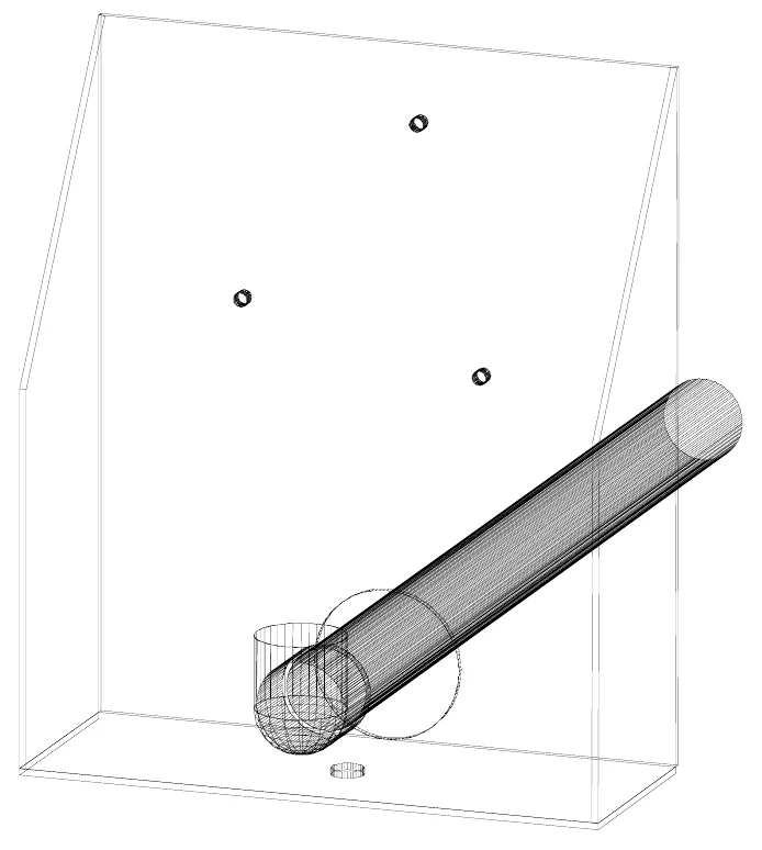
1.Cut a piece of ¾” conduit of sufficient length to reach from the horn mounting point to one of the holes in the plate below the upper access panel. 2.Attach the ¾” right angle male conduit connector to one end of the conduit and the ¾” straight male conduit connector to the other end. 3.Cut two pieces of wire of approximately 7 feet longer than the conduit. 4.Push the wires through the conduit. 5.Push the end of the conduit with the right angle male conduit connector through the 2” diameter hole in mounting bracket as seen in figure 12.
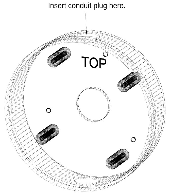
6.The weatherproof back box has two threaded conduit holes. Screw the provided conduit plug into the hole near the word “TOP” inside the weatherproof back box (figure 13).
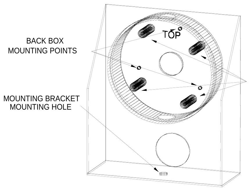
7.Feed the wires through the other back box conduit hole and screw the right angle conduit connector to the back box. 8.Attach the weatherproof back box to the mounting bracket using the provided 6-32 x 5/8” screws and 6-32 gold nuts as shown in figure 14.
9.Remove the horn signal mounting plate from the horn base by loosening the phillips head screw on the base. 10.The word “TOP” is stamped on the front side of the horn signal mounting plate. Pass the two wires that are inside the back box through the horn signal mounting plate center hole from the back side. 11.Align the holes in the horn signal mounting plate with the mounting screw holes in the back box bosses. The word “TOP” on the horn signal mounting plate and the back box should be oriented in the same direction and the screw hole on the bottom edge of the horn signal mounting plate should be directly over the gap in the back box gasket as seen in figure 15.
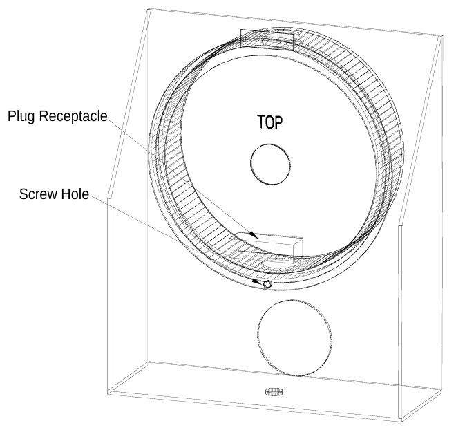
12.Fasten the horn signal mounting plate with the four 8-32 x 7/16” machine screws that are provided with the back box. 13.Crimp forked terminals on the ends of the two wires and attach them to the plug receptacle. 14.Slide the slot on the side of the horn base over the tab on the horn signal mounting plate and tighten the phillips head screw on the other side of the horn base. 15.Fasten the horn assembly to the scoreboard using the mounting bolt from the scoreboard. 16.Crimp forked terminals on the ends of the two wires that protrude out of the other end of the conduit. 17.Pass the wires through one of the holes in the plate below the upper access panel. 18.Fasten the conduit connector to the plate and connect the wires to T-2.
ScoreLink 300 The ScoreLink 300 RF MODEM SYSTEM is designed to eliminate the control cable between the scoreboard and the control console on Electro-Mech Scoreboard MM and MP series scoreboards. If you have purchased this accessory, disregard the section of this manual titled Control Cable Installation. Refer to the ScoreLink 300 RF MODEM SYSTEM OWNER’S HANDBOOK for installation instructions.
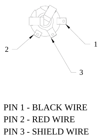
Control Cable Installation The control cable connects the scoreboard to the control console. Install the control cable in conduit. If the cable is ever damaged, it is easier and less expensive to replace a cable in conduit. A small junction box with a ¼” stereo jack mounted on the face plate is attached to the control cable at the point of operation of the scoreboard. This junction box should be securely mounted in a clean, dry area within ten feet of the rear of the control console. Most customers order the control cable with the junction box attached. Some customers prefer to attach the junction box after the cable is installed. Those customers must solder the control cable to the ¼” stereo jack. Figure 16 shows the control cable wire connection points on the rear of the ¼” stereo jack.
The following steps describe how to connect the control cable to the scoreboard:
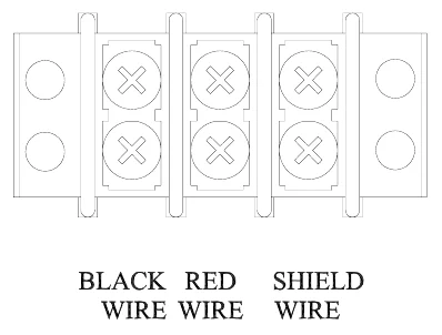
1.At the rear of the scoreboard feed the control cable one of the holes in the plate below the access panel. 2.Crimp fork terminals to the control cable wires and the shield. 3.Connect the control cable to T1 terminal block on the junction chassis according to figure 17.
4.Reinstall the access panel.
Control Console Connections The 10 ft. extension cable has two molded ¼” stereo plugs attached to it. It is used to connect the control console to the junction box. The following steps describe how to connect the control console:
1.Plug one end of the extension cable into ¼” stereo jack on the junction box or the ScoreLink 300 Transmitter, if purchased. 2.Plug the other end into the ¼” stereo jack mounted on the control console back plate. 3.Plug the control console power cord into a grounded NEMA 5-15R 120 VAC receptacle.
This product is equipped with a 3-wire grounding type plug, a plug having a third (grounding) pin. This plug will only fit into a grounding-type power outlet. This is a safety feature. If you are unable to insert the plug into the outlet, contact a qualified electrician to replace your obsolete outlet. Do not defeat the purpose of the grounding- type plug.
SCOREBOARD STARTUP
1.Place the power disconnect for the scoreboard in the ON position. 2.Plug one end of the extension cable into ¼”stereo jack on the junction box or the ScoreLink 300 Transmitter, if purchased. 3.Plug the other end into the ¼”stereo jack mounted on the control console back plate. 4.Plug the control console power cord into a grounded NEMA 5-15R 120 VAC receptacle. 5. If a ScoreLink 300 RF MODEM SYSTEM is installed with this scoreboard, plug the wall mount DC power supply into a grounded NEMA 5-15R 120 VAC receptacle and the male plug on the end of the attached cable into the Power jack on the Transmitter.
GAME TIME OPERATION
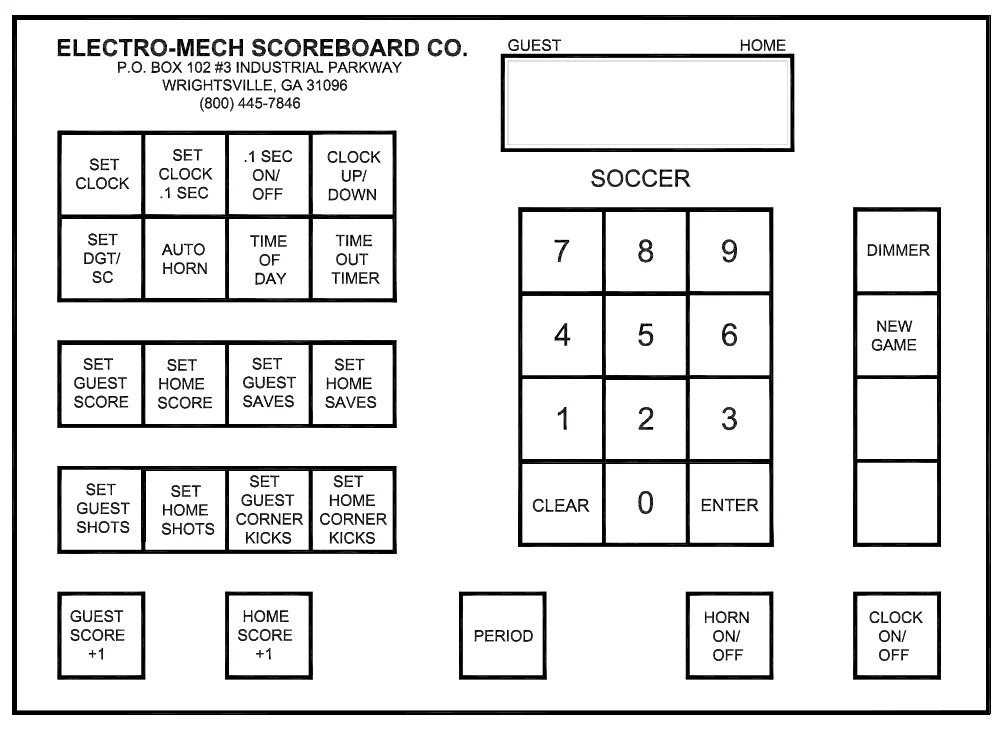
This scoreboard is operated with a 37-key control console. Figure 18 shows the keypad layout on the control console.
Immediately after the control console power cord is plugged into a 120 VAC source, the console LCD display will read:
ELECTRO-MECH VER SCOREBOARD SK2
After a few seconds the display will read:
00
00 D15:00 0 00
00
The scoreboard will display:
CLOCK – 15:00 GUEST SCORE – 0 HOME SCORE – 0 GUEST SHOTS – 0 HOME SHOTS – 0 GUEST C KICKS – 0 HOME C KICKS – 0
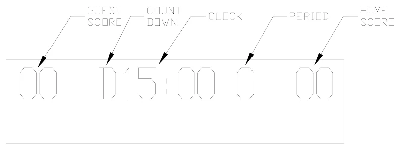
The control console LCD display shows the same information as the scoreboard. Note: In some functions a 0 will be blanked on the scoreboard, but not on the console. Figure 19 explains the LCD display layout.
Control Console Key Functions
1.SET CLOCK – This key sets the time displayed on the scoreboard clock. Press [SET CLOCK]. The console LCD display will read:
00 D15:00 0 00 SET CLK <00:00>
Pressthe keypad numbers for the time, [ENTER]. Example: Press [SET CLOCK], [6], [0], [0], [0], [ENTER]on the control console. 60:00 will be displayed on the clock section of the scoreboard.
2.SET CLOCK .1 SEC – This key is used to set the scoreboard clock to a time less than one minute when tenth of a second accuracy is required. Press [SET CLOCK .1 SEC]. The console LCD display will read:
00 D15:00 0 00 SET SEC <00.0>
Pressthe keypad numbers for the time, [ENTER]. Example: Press [SET CLOCK .1 SEC], [5], [3], [8], [ENTER]on the control console. 53.8 will be displayed on the clock section of the scoreboard.
3..1 SEC ON/OFF – This key is used to enable or disable the display of tenths of seconds on the scoreboard. The use of this key has a visible effect on the scoreboard only if the game clock is less than one minute. This mode is enabled when the control console is turned on. If it is disabled, the LCD display on the control console will still show 1/10th second timing, but the scoreboard will not display it. To turn this function off, press [.1 SEC ON/OFF]. The console LCD display will read:
CLOCK .1 SEC
.1 SEC OFF <0>
Press [0], [ENTER]on the control console.
4.CLOCK UP/DOWN – The clock can be set up to either count up or count down. The control console is set to the clock down mode when it is turned on. To make the clock count up, press [CLOCK UP / DOWN]. The console LCD display will read:
GAME CLOCK
GAME UP <1> CLOCK DOWN <0>
Press [1], [ENTER]on the control console. The letter D in front of the game time on the console LCD will be replaced with the letter U to indicate that the clock is in the count up mode. To reset the clock to count down mode, press [CLOCK UP / DOWN], [0], [ENTER]on the control console.
5.SET DGT/SC – The console is programmed with two delay of game timers. The delay of game timers should be set prior to the start of a game. Delay of Game Timer 1 is preset to 30 seconds. Delay of Game Timer 2 is preset to 5 seconds. To change either one of these times, press [SET DGT/SC]. The console LCD display will read:
00 D15:00 0 00 DELAY TIME1 <30>
Press the keypad numbers to set Delay of Game Timer 1, [ENTER]. The LCD display will then read:
00 D15:00 0 00 DELAY TIME2 <05>
Press the keypad numbers to set Delay of Game Timer 2, [ENTER].
6.AUTO HORN – This key allows the operator to control the end of period horn and the time out horn. The horn sounds for two seconds when the clock reaches 0:00 at the end of the period. The end of period horn can be disabled by pressing [AUTO HORN]. The console LCD display will read:
GAME PRESS<1>ON HORN PRESS<0>OFF
Press [0], [ENTER]to disable the horn. The console LCD display will then read:
T-O PRESS<1>ON HORN PRESS<0>OFF
The time out horn is normally disabled. To enable the horn to sound at the end of the time out, press[1], [ENTER]on the control console.
7.TIME OF DAY – The time of day can be displayed on the clock section of the scoreboard. THE GAME CLOCK WILL BE INOPERABLE UNTIL THE TIME OF DAY FUNCTION IS TURNED OFF. To turn the time of day clock on, press [TIME OF DAY]. The console LCD display will read:
TIME OF ON (1) DAY CLOCK OFF(0)
Press [1], [ENTER] on the control console. The console LCD display will then read:
00 C12:00 0 00 SET CLK <12:00>
Press the keypad numbers for the time, [ENTER]. The letter C will be displayed on the console LCD display to the left of the time to indicate that the time of day function is active. The scoreboard will display the time of day.
8.TIME OUT TIMER – To set the Time Out Timer, press [TIME OUT TIMER]. The console LCD display will read:
00 D15:00 0 00 SET T-O <1:00>
Press the keypad numbers for the time, [ENTER]. After the ENTER key is pressed, the letter T is displayed to the left of the time on the LCD display and the Time Out Timer immediately begins to count down to 0. The scoreboard will not display the Time Out time. To exit the Time Out Timer function before 0, press [TIME OUT TIMER], [ENTER].
9.SET GUEST SCORE – To set the visitor score, press [SET GUEST SCORE]. The console LCD display will read:
00 D15:00 0 00 GUEST SCORE <00>
Press the keypad numbers for the score, [ENTER]. EXAMPLE: To set the visitor score to 53, press [SET GUEST SCORE], [5], [3], [ENTER].
10.SET HOME SCORE – To set the home score, press [SET HOME SCORE]. The console LCD display will read:
00 D15:00 0 00 HOME SCORE <00>
Press the keypad numbers for the score, [ENTER]. EXAMPLE: To set the home score to 75, press [SET HOME SCORE], [7], [5], [ENTER].
11.SET GUEST SHOTS – To set the visitor shots, press [SET GUEST SHOTS]. The console LCD display will read:
00 D15:00 0 00 GUEST SHOTS <00>
Press the keypad numbers for the number of shots, [ENTER]. EXAMPLE: To set the visitor shots to 1, press [SET GUEST SHOTS], [1], [ENTER].
12.SET HOME SHOTS – To set the home shots, press [SET HOME SHOTS]. The console LCD display will read:
00 D15:00 0 00 HOME SHOTS <00>
Press the keypad numbers for the number of shots, [ENTER]. EXAMPLE: To set the home shots to 2, press [SET HOME SHOTS], [2], [ENTER].
13.SET GUEST CORNER KICKS – To set the visitor corner kicks, press [SET GUEST CORNER KICKS]. The console LCD display will read:
00 D15:00 0 00 GUEST KICKS <00>
Press the keypad numbers for the number of corner kicks, [ENTER]. EXAMPLE: To set the visitor corner kicks to 6, press [SET GUEST CORNER KICKS], [6], [ENTER].
14.SET HOME CORNER KICKS – To set the home corner kicks, press [SET HOME CORNER KICKS]. The console LCD display will read:
00 D15:00 0 00 HOME KICKS <00>
Press the keypad numbers for the number of corner kicks, [ENTER]. EXAMPLE: To set the home corner kicks to 15, press [SET HOME CORNER KICKS], [1], [5], [ENTER].
15.GUEST SCORE +1 – This key is used to increment the visitor score by 1.
16.HOME SCORE +1 – This key is used to increment the home score by 1.
17.PERIOD – This key is used to increment the period by 1.
18.HORN ON/OFF – This key is used to toggle the horn on and off.
19.CLOCK ON/OFF – This key is used to start and stop the clock.
20.NEW GAME – This key is used to reset all the scoreboard functions to their default settings. To reset the scoreboard, press [NEW GAME]. The console LCD display will read:
RESET YES<1> SCOREBOARD NO<0>
Press [1], [ENTER]on the control console. The scoreboard will reset its functions.
21.DIMMER – This key is used to dim all the scoreboard lamps. To dim the scoreboard lamps, press [DIMMER]. The console LCD display will read:
DIMMER ON
YES<1> NO<0>
Press [1], [ENTER]on the control console. The scoreboard will dim its lamps.
The SET GUEST SAVES and SET HOME SAVES keys are not used with the MP-386 scoreboard.
Hand Held Clock Control Unit Operation The hand held clock control unit has an attached cable that is plugged into a jack on the control console back plate labeled Clock Hand held. It has one button that is used to toggle the clock on and off.
You should reset the scoreboard each time that it is turned on. Test out all the functions to ensure that the scoreboard is operating properly.
SCOREBOARD SHUTDOWN
1. 2. 3. 4.
1.Place the power disconnect for the scoreboard in the OFF position. 2.Unplug the control console power cord. 3.Unplug the extension cable. 4.If a ScoreLink 300 RF MODEM SYSTEM is installed with this scoreboard, unplug the Transmitter’s wall mount power supply. 5.Store the control console and ScoreLink 300 Transmitter is a dry location. These units are not waterproof.
Proper scoreboard shutdown will help protect the scoreboard and control console from power surges and lightning strikes.
SERVICING THE SCOREBOARD
While your scoreboard was designed for years of trouble-free operation, some problems may occasionally occur. Electro-Mech Scoreboard Company offers onsite service in some areas. In other areas, we can help you contact an independent service technician. In areas in which service is not available from Electro-Mech Scoreboard Company, we will make every effort to answer your questions. Our trained personnel at Electro-Mech Scoreboard Company are ready to answer your questions from Monday to Friday during the hours of 8 AM to 5 PM Eastern Standard Time. Be sure to know your scoreboard model number when calling. Scoreboard replacement parts are always available. Damaged parts can usually be repaired at a significant cost savings. Our convenient toll free number is listed at the bottom of every page in this manual.
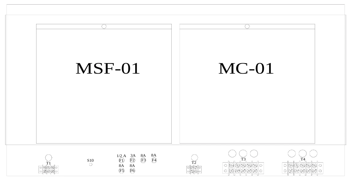
Figure 20 shows the components behind the upper access panel.
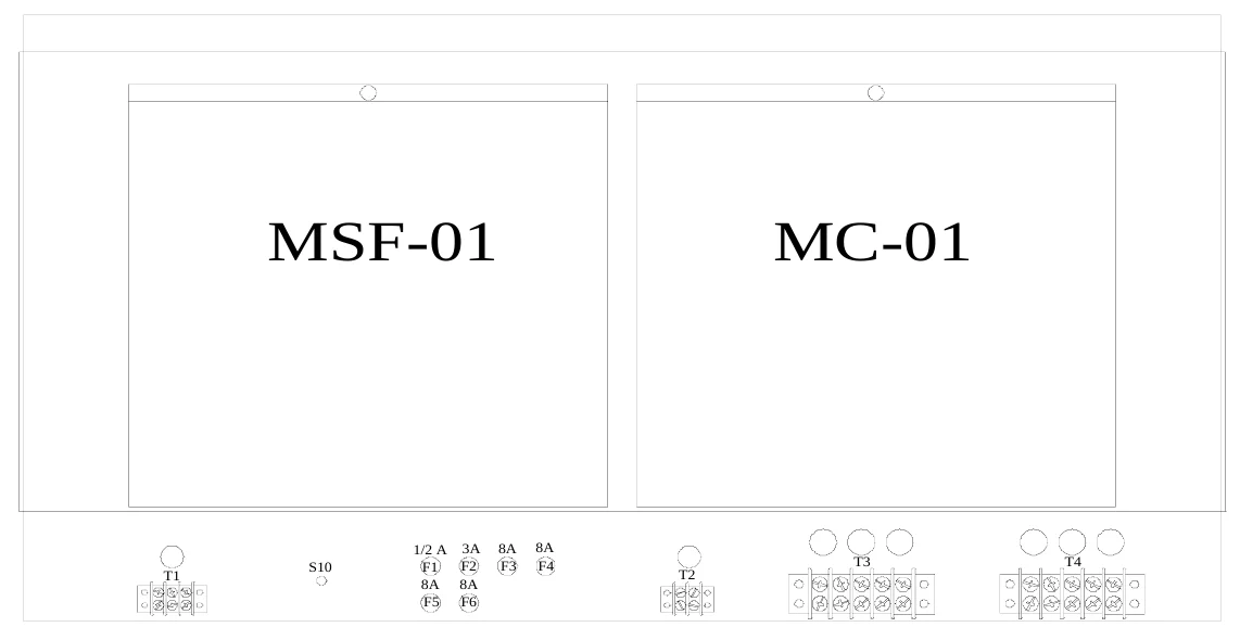
The plug in module MSF-01 operates visitor and home score. The plug in module MC- 01 operates the clock and the horn.
FUSES
| FUSES | |||
|---|---|---|---|
| FUSE RATING | FUNCTION | ||
| F1 1/2 A 250 V CONTROL LINE | |||
| F2 | 3 A 250 V | HORN | |
| F3 | 8 A 250 V | MINUTES | |
| F4 | 8 A 250 V | SECONDS | |
| F5 | 8 A 250 V VISITOR SCORE | ||
| F6 | 8 A 250 V | HOME SCORE |
CONNECTION POINTS
TERMINAL STRIP FUNCTION T-1 control cable connection T-2 power cable to horn T-3 MOV (surge protection) T-4 power cable connection S-10 test jack
Figure 21 shows the components behind the lower access panel.
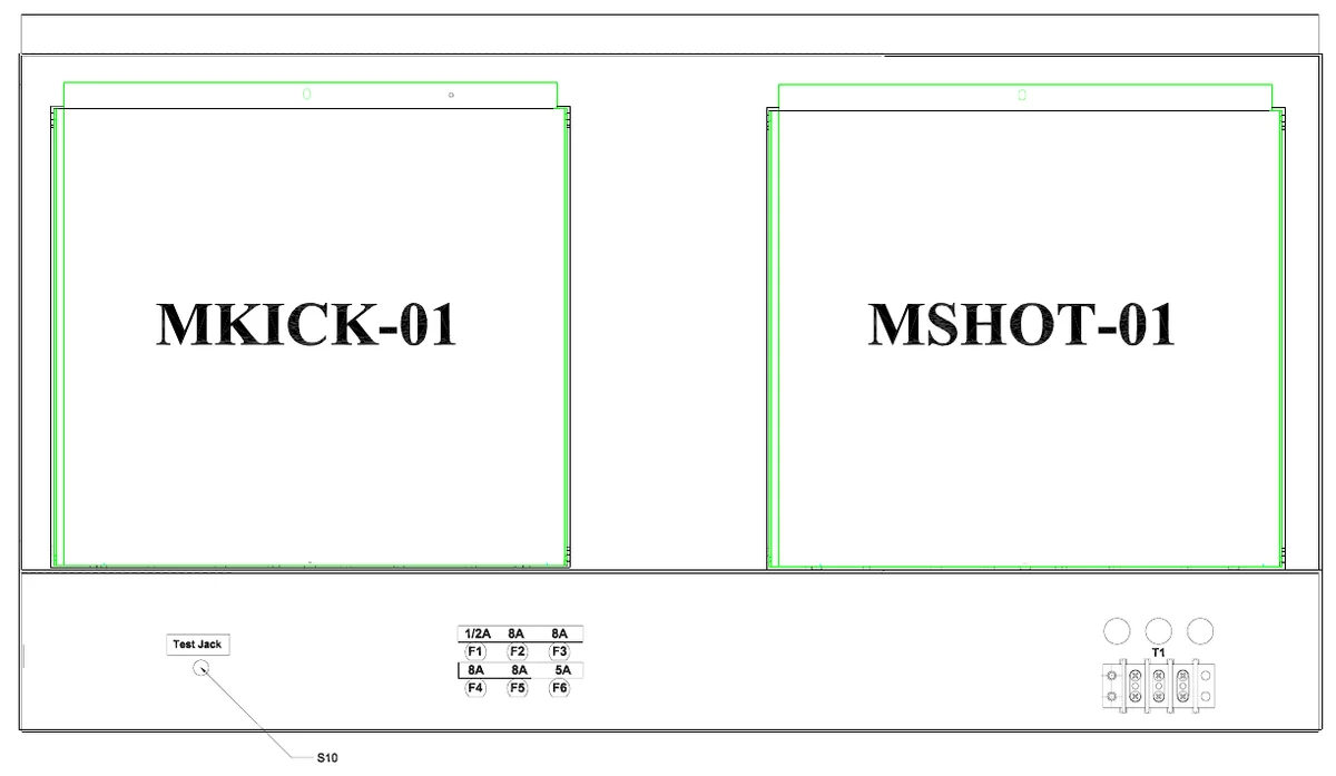
The plug in module MKICK-01 operates the visitor and home corner kicks. The plug in module MSHOT-01 operates the visitor and home shots, and the period. T-1 is not normally used. It can be used to help troubleshoot a scoreboard that has no power to the lower section.
FUSES
| FUSES | |||
|---|---|---|---|
| FUSE RATING | FUNCTION | ||
| F1 1/2 A 250 V CONTROL LINE | |||
| F2 | 8 A 250 V | HOME SHOTS | |
| F3 | 8 A 250 V VISITOR SHOTS | ||
| F4 | 8 A 250 V VISITOR KICKS | ||
| F5 | 8 A 250 V VISITOR KICKS | ||
| F6 | 5 A 250 V | PERIOD |
CONNECTION POINTS
TERMINAL STRIP T-1
FUNCTION test power connection S-10 test jack
PLUG IN MODULE REPLACEMENT
Each module has four bottom plugs that mate with sockets in the scoreboard. A screw located at the top of the module holds it against the scoreboard cabinet. Simply remove the screw and pull the module upward to unseat the module. To avoid damage to the plug in module,always turn off the power to the scoreboard when removing or replacing it.
LAMP REPLACEMENT
Remove the protective mask covering each lamp bank to access the lamps. To avoid damage to the plug in module,always turn off the power to the scoreboard when changing lamps. We recommend using a felt pen or tape to mark lamps that will not light. The scoreboard uses 15 watt 120 VAC frosted medium based appliance lamps (also known as 15A15IF lamps).Never replace these with higher wattage lamps.
ELECTRO-MECH SCOREBOARD CO. FIVE YEAR LIMITED WARRANTY
THE ELECTRICAL COMPONENTS OF ALL ELECTRO-MECH SCOREBOARDS ARE GUARANTEED FOR A PERIOD OF FIVE (5) YEARS FROM THE DATE OF INVOICE AGAINST DEFECTS IN WORKMANSHIP OR MATERIAL AND WILL BE REPLACED OR REPAIRED WITHOUT COST TO THE OWNER PROVIDED THE EQUIPMENT OR PARTS ARE RETURNED POSTAGE-PAID TO THE FACTORY IN WRIGHTSVILLE, GA. SHIPPING BACK TO THE OWNER WILL BE VIA UPS GROUND SERVICE EXCEPT WHEN AIR OR SPECIAL METHOD OF RETURN IS SPECIFIED BY THE OWNER, IN WHICH CASE SHIPPING WILL BE FREIGHT COLLECT.
EXCLUDED FROM THIS WARRANTY ARE LAMPS, FUSES AND SOCKETS.
THIS WARRANTY DOES NOT INCLUDE LABOR CHARGES INCURRED IN THE REMOVAL OF COMPONENT PARTS, SERVICE CALLS, OR DAMAGES RESULTING FROM IMPROPER INSTALLATION, IMPROPER OPERATION, OR PROBLEMS CAUSED BY ANY REPAIR, ALTERATION OR MODIFICATION OF THE SCOREBOARD NOT PERFORMED BY ELECTRO-MECH.
EQUIPMENT WHICH IS SUBJECTED TO ACCIDENT, NEGLECT, ABUSE, MISUSE OR OTHER NATURAL DISASTERS, INCLUDING BUT NOT LIMITED TO FIRE, WIND, LIGHTNING, OR FLOOD, IS NOT COVERED BY THIS GUARANTEE.