
Home / Documentation / Accessory manual
Download the original PDF (303 kB)
This page reproduces the text of the PDF above without alteration, so the document can be read, searched and linked to directly.
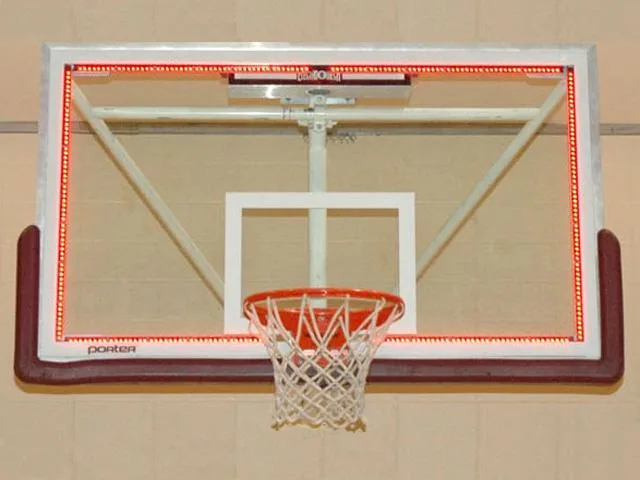
Thank you for choosing this product for your athletic complex. We are confident that it will give many years of reliable service.
Rev. 3 Revised: 9/01/09 Rev. 4 Revised: 7/06/10 Rev. 5 Revised: 8/16/11 Rev. 6 Revised: 9/7/11
SPECIFICATIONS
GENERAL: This accessory includes the backboard LED array segment brackets (one TOP bracket, two BOTTOM brackets, and two SIDE brackets), a wire assembly, and a transformer enclosure assembly (If transformer is needed for your application).
DIMENSIONS: TOP BRACKET: 66” L x 1” W x 1” D; SIDE BRACKETS: 30.5” L x 1” W x 1” D; SIDE BRACKETS: 20.25” L x 1” W x 1” D
ARRAY WEIGHT: 3 lbs
CONSTRUCTION: The backboard LED array consists of five segments. Each segment consists of a number of printed circuit board assemblies mounted on a formed aluminum bracket. The brackets are attached to the backboard with very high bond foam tape. The transformer is mounted in a NEMA 4X enclosure (If transformer is needed for your application).
DISPLAY: The backboard LED array illuminates when the basketball scoreboard game clock reaches 0 seconds. It will also illuminate when the scoreboard’s control console HORN key is pressed.
SEGMENTS: Precision optical performance red oval light emitting diodes mounted on printed circuit boards form the segments. Each printed circuit board assembly includes nine high intensity light emitting diodes. The light emitting diodes are spaced 0.6” apart.
POWER REQUIREMENTS:
BACKBOARD LIGHT ASSEMBLY: 18.9 VDC, 7.7A DC each. The backboard LED array is powered by a compatible Electro-Mech Scoreboard shot timer.
TRANSFORMER ENCLOSURE ASSEMBLY: 120 VAC stepped down to 15 VAC, .75A each at 120 VAC, 6.0 A each at 15 VAC, 60 Hz. The backboard LED array is powered by a compatible Electro-Mech basketball scoreboard.
WARRANTY: Five year limited warranty.
OVERVIEW
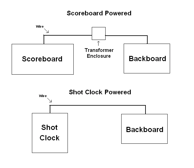
Backboard lights can be powered by a dedicated output either on any basketball scoreboard or a shot clock with a CPC plug. If they are powered by a basketball scoreboard, a transformer enclosure is required between the scoreboard and the backboard lights assembly. If they are powered by a shot clock with a CPC plug, the shot clock is connected directly to the backboard lights assembly. For both installations the backboard light brackets are installed the same.
BACKBOARD LED ARRAY INSTALLATION INSTRUCTIONS
First determine which configuration you are installing.
If you have a shot clock with a CPC connector on the top (see Fig. 1), then follow the instructions for “Shot Timer Powered Backboard Lights”.
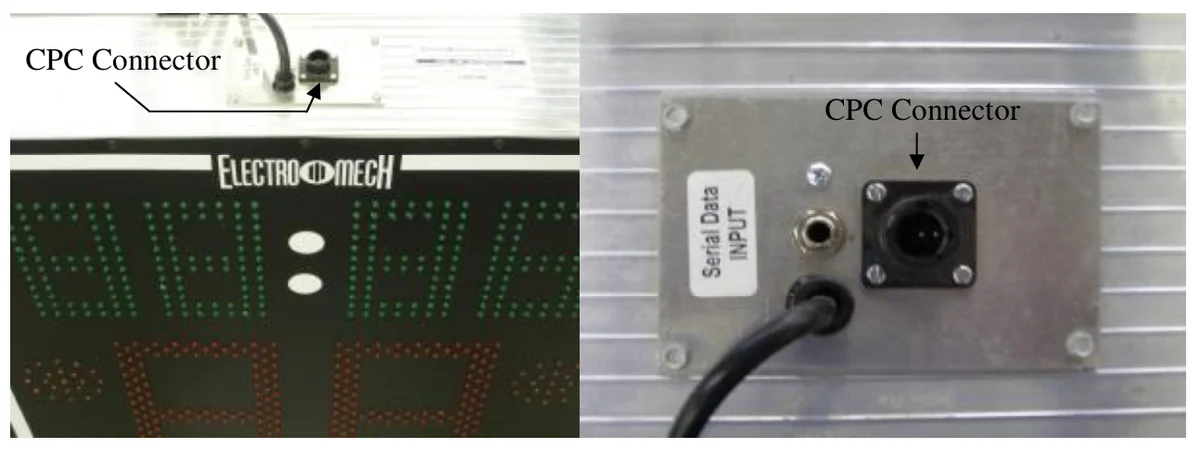
Left: 2180 CPC Location, Right: Close-up of CPC Connector
If you have any other configuration follow the instructions for “Scoreboard Powered Backboard Lights”.
For both types the LED backboard light brackets will be installed the same way as follows.
LED Backboard Light Brackets
1.CLEAN SURFACE OF BACKBOARD BEFORE APPLYING BRACKETS!
2.Remove the white liner from the high bond tape on the backboard light brackets labeled
SIDE and mount them along the left and right side of the backboard glass (inside the white
tape line). Be sure that the LEDs are visible through the backboard glass.
3.Mount the backboard light bracket labeled TOP LEFT in the same manner as in step 1 along
the top left side of the backboard (as viewed from the rear of the backboard).
4.Mount the backboard light bracket labeled TOP RIGHT in the same manner as in step 1
along the top right side of the backboard (as viewed from the rear of the backboard).
5.Mount the backboard light bracket labeled BOTTOM LEFT in the same manner as in step 1
along the bottom left side of the backboard (as viewed from the rear of the backboard).
6.Mount the backboard light bracket labeled BOTTOM RIGHT in the same manner as in step
1 along the bottom right side of the backboard (as viewed from the rear of the backboard).
7.Connect all wire harnesses in the four corners of the backboard as shown in Fig. 2
8.Continue to the next appropriate section for your configuration.
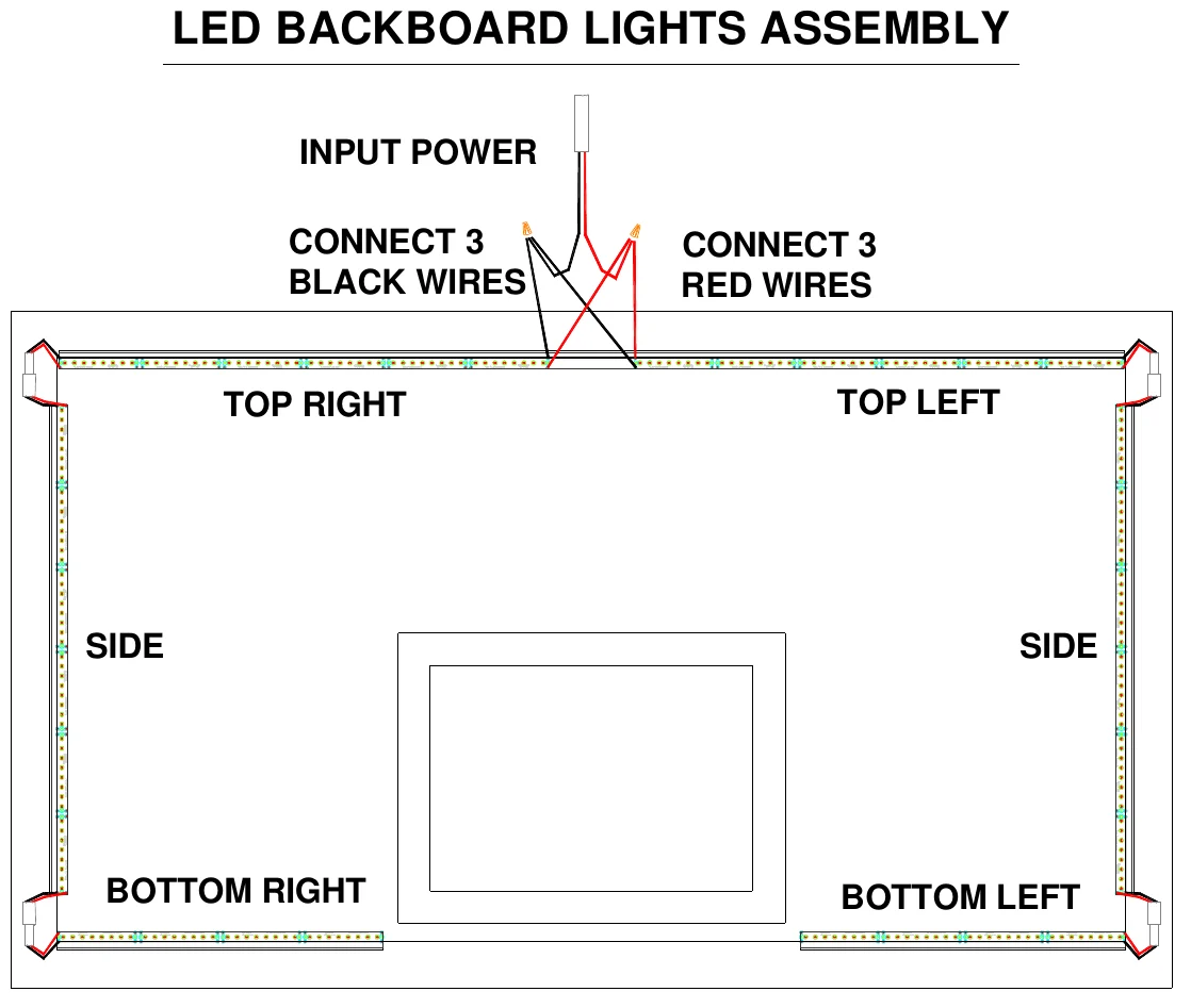
Front view of bracket assembly (Looking through goal side of backboard)
Shot Timer Powered Backboard Lights
1.Plug one side of supplied CPC cable into shot clock.
2.Route cable from shot clock to the four wires on the TOP bracket.
3.Using the wire nuts connect the wires of this cable to the LED backboard lights as shown in
Fig. 2.
4.Installation complete.
Scoreboard Powered Backboard Lights
1.Mount the transformer enclosure assembly within 25 ft. of the backboard. Some mounting hardware has been provided for attachment to a pole.
2.Open the transformer enclosure assembly door (see Fig 3).
Run 120VAC wires through this grommet (White and Black wires)
Run 24VAC wires through this grommet (Red and Black wires)
10A FUSE
Tie wires here with wire tie
SCOREBOARD POWERED BACKBOARD LED ARRAY
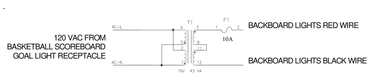
Top: Transformer Enclosure Assembly Bottom: Transformer Enclosure Assembly Schematic
3.Cut a length of the supplied cable to connect from inside the transformer enclosure assembly to the goal light receptacle on the right side of a compatible Electro-Mech Scoreboard Co. scoreboard (see Fig. 4).
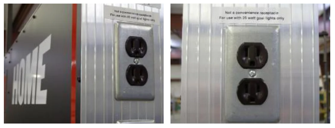
Left: Goal Light Receptacle on side of Scoreboard, Right: Close-up of Goal Light Receptacle
4.Install the cable between the transformer enclosure assembly and the goal light receptacle. 5.At the scoreboard end of the cable, attach the supplied plug (DO NOT PLUG IN UNTIL INSTALL IS COMPLETE TO AVOID ELECTRIC SHOCK). 6.At the other end, insert the cable in one of the holes in the transformer enclosure assembly (see Fig. 3). 7.Use a wire nut to connect the black wire from inside the transformer enclosure assembly (labeled AC-L) to either wire in the cable (see Schematic in Fig. 3). 8.Use a wire nut to connect the white wire from inside the transformer enclosure assembly (labeled AC-N) to other wire in the cable (see Schematic in Fig. 3). 9.Cut a length of the supplied cable to connect from inside the transformer enclosure assembly to the TOP bracket of the backboard. 10.Install the cable between the transformer enclosure assembly and the goal light receptacle. 11.Insert the cable in one of the holes in the transformer enclosure assembly. 12.Use a wire nut to connect the red wire from inside the transformer enclosure assembly (labeled BACKBOARD LIGHTS RED WIRE) to either wire in the cable (see Schematic in Fig. 3). 13.Use a wire nut to connect the black wire from inside the transformer enclosure assembly (labeled BACKBOARD LIGHTS black WIRE) to other wire in the cable (see Schematic in Fig. 3). 14.Fasten both cables to the black cable tie mounts inside the enclosure assembly using a plastic tie wrap. 15.Close the transformer enclosure assembly door. 16.At the TOP backet of the backboard, connect the wires of the cable to the LED backboard lights as shown in Fig. 2. 17.Insert the plug into the scoreboard goal light receptacle (see Fig. 4). 18.Installation complete.
ELECTRO-MECH SCOREBOARD CO. FIVE YEAR LIMITED WARRANTY
THE ELECTRICAL COMPONENTS OF ALL ELECTRO-MECH SCOREBOARDS ARE GUARANTEED FOR A PERIOD OF FIVE (5) YEARS FROM THE DATE OF INVOICE AGAINST DEFECTS IN WORKMANSHIP OR MATERIAL AND WILL BE REPLACED OR REPAIRED WITHOUT COST TO THE OWNER PROVIDED THE EQUIPMENT OR PARTS ARE RETURNED POSTAGE-PAID TO THE FACTORY IN WRIGHTSVILLE, GA. SHIPPING BACK TO THE OWNER WILL BE VIA UPS GROUND SERVICE EXCEPT WHEN AIR OR SPECIAL METHOD OF RETURN IS SPECIFIED BY THE OWNER, IN WHICH CASE SHIPPING WILL BE FREIGHT COLLECT.
EXCLUDED FROM THIS WARRANTY ARE FUSES.
THIS WARRANTY DOES NOT INCLUDE LABOR CHARGES INCURRED IN THE REMOVAL OF COMPONENT PARTS, SERVICE CALLS, OR DAMAGES RESULTING FROM IMPROPER INSTALLATION, IMPROPER OPERATION, OR PROBLEMS CAUSED BY ANY REPAIR, ALTERATION OR MODIFICATION OF THE SCOREBOARD NOT PERFORMED BY ELECTRO-MECH.
EQUIPMENT WHICH IS SUBJECTED TO ACCIDENT, NEGLECT, ABUSE, MISUSE OR OTHER NATURAL DISASTERS, INCLUDING BUT NOT LIMITED TO FIRE, WIND, LIGHTNING, OR FLOOD, IS NOT COVERED BY THIS GUARANTEE.