
Home / Documentation / Owner's manual
Download the original PDF (1056 kB)
This page reproduces the text of the PDF above without alteration, so the document can be read, searched and linked to directly.
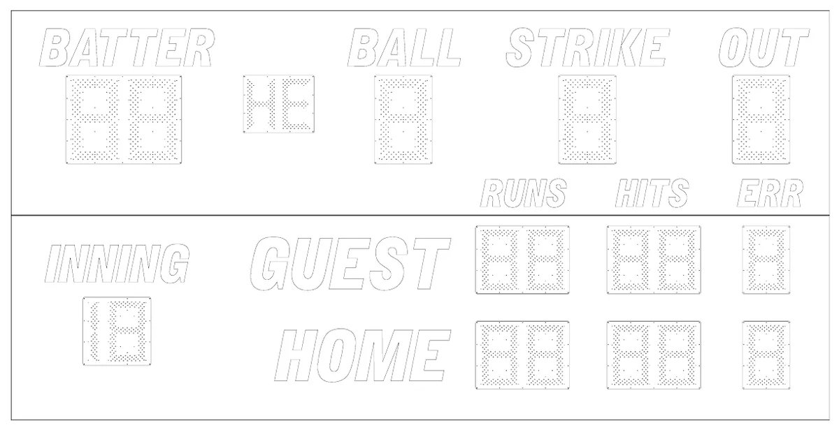
1480 BASEBALL SCOREBOARD
OWNER’S HANDBOOK
Thank you for choosing an Electro-Mech Scoreboard for your athletic complex. We are confident that your new scoreboard will give many years of reliable service.
Rev. 8 Revised: 01/26/2007
1480 BASEBALL SCOREBOARD SPECIFICATIONS
GENERAL: This ETL listed scoreboard includes the scoreboard cabinet, mounting hardware, control console, control cable (sold separately), 10 ft. extension cable, and junction box.
DIMENSIONS: 20’ L x 10’ H x 6” D (two cabinets which measure: 20’ x 5’ x 6”)
WEIGHT:625 lbs
SCOREBOARD CONSTRUCTION: The scoreboard consists of two cabinets. The frame is made from extruded aluminum. The face and back are made from aluminum sheet. The face and masks are finished with enamel paint. Black is the standard color. The captions are white.
DISPLAY: The 1480 scoreboard displays GUEST and HOME RUNS and HITS to 99, GUEST and HOME ERRORS to 9, BATTER number to 99, INNING to 19, BALLS, STRIKES, OUTS, HIT, and ERROR.
DIGITS AND INDICATORS: Red light emitting diodes mounted on printed circuit boards form the digits and indicators. The BATTER number, BALL, STRIKE, OUT digits are 24” tall. The INNING, total RUNS, HITS, and ERRORS digits are 18” tall. The hit (H) indicator and error (E) indicator are 15” tall.
POWER REQUIREMENTS: Scoreboard - 120 VAC, 1.9 A, 60 Hz. Control Console - 120 VAC, 0.5 A, 60 Hz
SCOREBOARD ELECTRONICS: 100% solid state fully enclosed.
CONTROL CONSOLE: The control console features a microprocessor, 37 key sealed membrane keypad, a LCD display and an attached 6 foot power cord. The console housing consists of ABS plastic base and top pieces with a steel back plate.
CONTROL CABLE: The cable has two 22 AWG stranded copper conductors with semi-rigid PVC insulation. It also has a braided shield and a foil shield. The polyethylene jacket is rated at 300 volts. The cable is direct burial rated and measures approximately ¼” in diameter. This item is sold separately from the scoreboard.
JUNCTION BOX AND EXTENSION CABLE: A 4 ¼” x 2 ¼” x 2” junction box with a ¼” stereo jack mounted on the face plate is attached to the control cable at the point of operation. A 10 ft. extension cable connects the control console to the junction box.
SCORELINK 300 RF MODEM SYSTEM: This accessory can be used in place of control cable and junction box for this scoreboard without internal modifications to the scoreboard or the control console. Refer to the SCORELINK 300 RF MODEM SYSTEM OWNER’S HANDBOOK for more information.
WARRANTY: Five year limited warranty.
SCOREBOARD INSTALLATION
This part of the manual describes the mechanical and electrical installation of the scoreboard.
One of the items listed below must be purchased in order to complete the installation:
- Control cable (length dependent upon installation site layout)
- ScoreLink 300 RF Modem System
Items not provided by Electro-Mech Scoreboard Company that are necessary for installation:
- Two posts
- Power cable to connect the scoreboard to the power source
- Grounding hardware
- A grounded NEMA 5-15R 120 VAC receptacle for the control console at the scorekeeper’s table.
Items not provided that are recommended by Electro-Mech Scoreboard Company for installation:
- A weatherproof power disconnect at the scoreboard
Electro-Mech Scoreboard Company performs installations in some areas. In other areas, we can help you contact an independent installer. In areas in which installation service is not available from Electro-Mech Scoreboard Company, we will make every effort to answer your installation questions. Qualified personnel should perform the scoreboard installation. Consult national and local codes before installation.
MECHANICAL INSTALLATION
The mechanical installation includes installing the posts and mounting the scoreboard and the optional top sponsor panels (if purchased) to the posts.
Post Installation The scoreboard mounts on two posts. Typically installers will use steel pipes or I-beams. In order to reduce the glare from the sun on the front of the scoreboard, position the posts so that the front of the scoreboard is angled away from the afternoon sun, if possible. The mounting hardware will accommodate posts up to 7 inches outer diameter. Sink the posts in reinforced concrete footings. Figure 1 shows the spacing of the posts for a 1480 scoreboard. The specifications for the posts and concrete footings are dependent upon the expected local wind and soil conditions, the height of the scoreboard from the ground, and the local building codes. Electro-Mech Scoreboard Company assumes no responsibility for the installation of scoreboards by others.
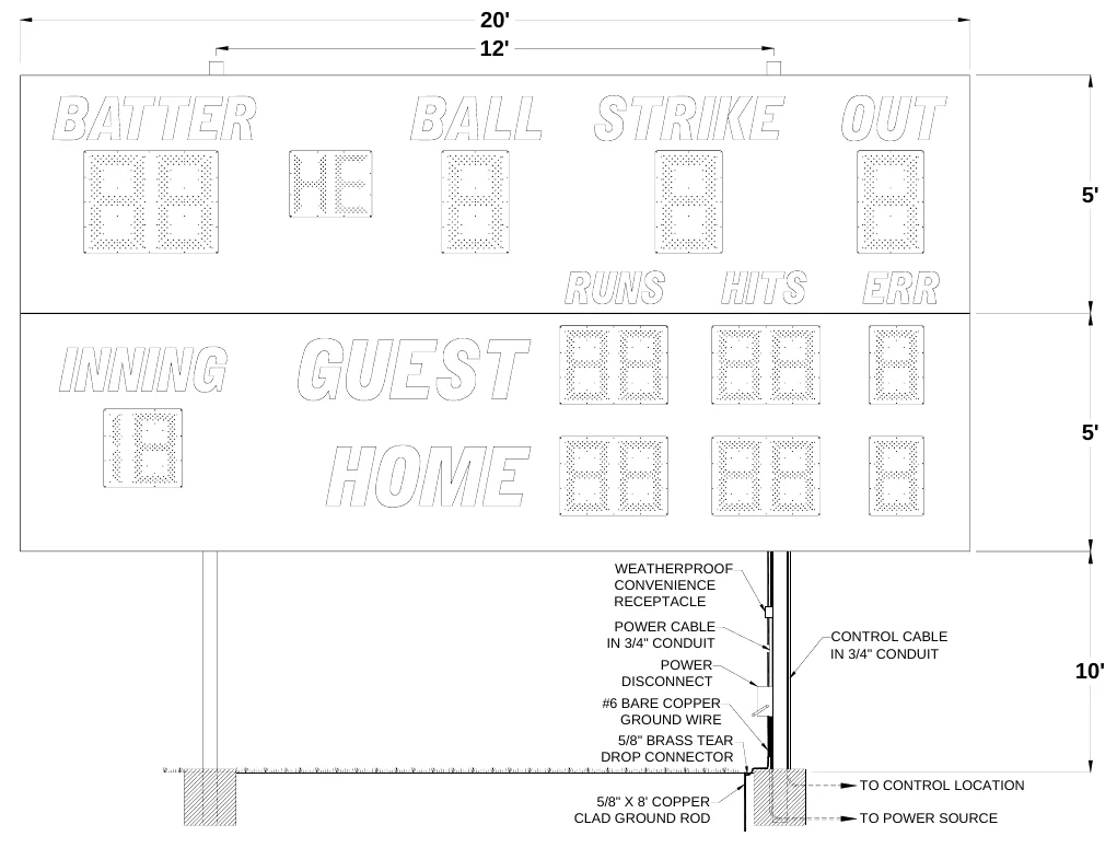
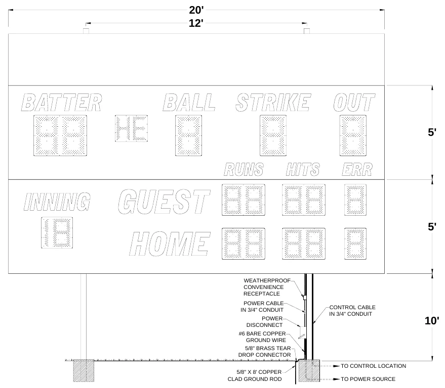
Figure 2 shows the spacing of the posts for a 1480 scoreboard with an optional top sponsor panel. This panel is a separate unit that mounts on the same posts as the scoreboard.
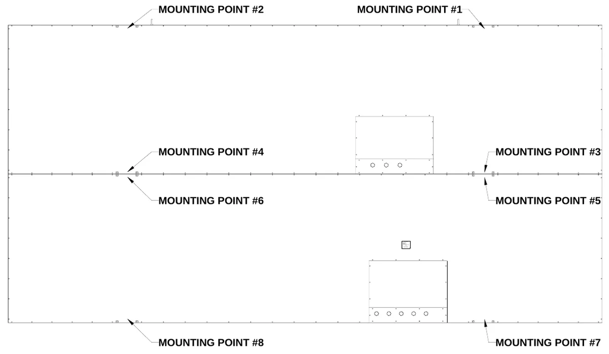
Mounting The Scoreboard The scoreboard is attached to the posts at eight points. Figure 3 shows the location of the mounting points on the rear of the scoreboard.
ELEC TR O-MECH SC OR EBOAR D C O.Date of Mfg.Serial N o. AB -Model No. MM-1000No. of l am phol ders 107120 VA C 60 H z 13.3 AReplace wit h 15 W lamp, maximum#3 In dustria l Par kway P .O. B ox 102Wr ightsville , GA 31096-0102 Electric shock hazard: Disconnectpower before ser vicing equipmentand local codes before installationCheck w ith the app licable stateCA UTION
MOUNTING HARDWARE
Eight sets of mounting hardware are provided to attach the scoreboard at these points. Additional hardware sets are provided to attach the optional sponsor panels, if ordered. A single set of mounting hardware for the scoreboard consists of a steel angle bracket, two threaded rods, two washers, and two nuts. A single set of mounting hardware for an optional top sponsor panel consists of a steel angle bracket, two threaded rods, four washers, and four nuts. Figure 4 shows an overhead cross section view and a side cross section view of the scoreboard attached to a post at a mounting point. A steel bar is riveted inside the scoreboard’s aluminum extrusion frame. The bar has two tapped holes. The threaded rods screw into these tapped holes. The washers and nuts are used to clamp the steel angle bracket against the steel post and hold the scoreboard in place.
4-Inch Steel Post
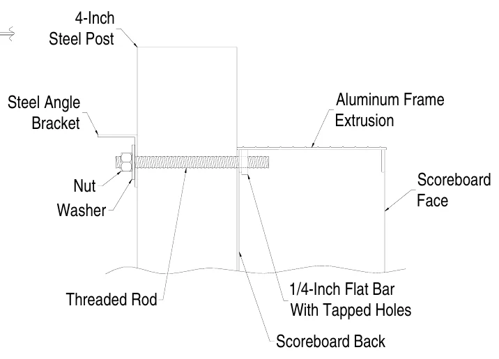
The following steps describe how to mount the scoreboard on the posts: 1.Place the lower section of the scoreboard against the posts on the ground. Make sure the mounting points are aligned with the posts. 2.If the eyebolts are installed in the upper section of the scoreboard, unscrew them and screw them into the lower section of the scoreboard. 3.Screw the threaded rods into the tapped holes in the scoreboard. 4.Place a steel angle bracket over the threaded rods at a mounting point. 5.Place a washer over each threaded rod. 6.Screw the nuts onto the threaded rods so that the bracket is loosely held in place. 7.Repeat steps 4 -6 at the other mounting points. 8.Raise the section into place and tighten the nuts to clamp it in place on the posts. 9.Unscrew the eyebolts from the lower section of the scoreboard and screw them into the upper section of the scoreboard. 10.Place the upper section of the scoreboard on top of the lower section. 11.Attach the mounting hardware by the same method as the lower section. 12.Tighten the nuts to clamp it in place on the posts.
Mounting The Optional Top Sponsor Panel Additional hardware sets are provided to attach the optional top sponsor panels, if purchased. The following steps describe how to mount the top sponsor panel on the posts:
1.
Raise the top sponsor panel in place above the scoreboard. Make sure the mounting points are aligned with the posts. Place the threaded rods through the mounting holes in the top sponsor panel at one mounting point. Place a washer over each threaded rod inside the frame of the top sponsor panel, and screw a nut onto each threaded rod behind the washers inside the frame of the top sponsor panel. Place a steel angle bracket over the threaded rods at a mounting point. Place a washer over each threaded rod. Screw a nut onto each threaded rod so that the bracket is loosely held in place. Repeat steps 2 - 6 at the other mounting points. Tighten the nuts to clamp it in place on the posts.
2. 3.
4. 5. 6. 7. 8.
ELECTRICAL INSTALLATION
We recommend a qualified electrician perform the needed electrical connections to ensure proper operation of the scoreboard. These connections include grounding the scoreboard, the upper scoreboard cabinet power and data connections, connecting the scoreboard to a power source, installing the ScoreLink 300 or the control cable, and connecting the control console.
| Ground Connection | ||
|---|---|---|
| The National Electrical Code | requires a scoreboard (electric sign) to be grounded. Grounding the | |
| scoreboard helps the scoreboard electronics operate properly and helps minimize damage if it is struck by | ||
| lightning. Metal posts do | not provide an adequate ground path. The following steps describe how to | |
| connect the scoreboard to the power source: | ||
| 1. | Drive one or more 5/8” x 8’ copper clad ground rods in the soil near the scoreboard. | |
| 2. | Connect #6 bare copper wire to the ground rods using 5/8” brass tear drop connectors. | |
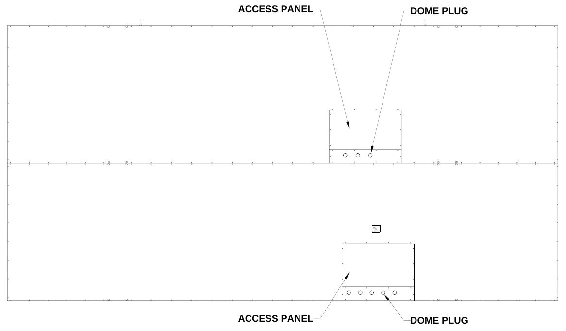
| 3. | Remove the rear access panels and the dome plugs on the plates below the access panels. Figure 5 | |
| shows the location of the access panels and the dome plugs. |
ELE CTRO- MEC H SCO REBOA RD C O.Se rial No. AB -Mode l N o. MM-1 00 0No. of la mpholde rs 10 71 20 VAC 6 0 Hz 1 3. 3 ADa te of Mf g.Re pla ce wit h 15 W lamp, ma ximum#3 Indus trial P ark w ay P .O . Box 102Wrights v ille, G A 31096-0102 Elect ric s hoc k hazard: Dis connec tpower befor e s erv ic ing equipmentand local codes before installationCheck with the applic able s tateCAU TI ON
4.
Connect the ground conductor to the ground lugs located behind the access panels.
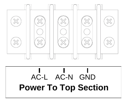
Power Connections to Upper Scoreboard Cabinet The following steps describe how to connect power to the upper scoreboard cabinet: 1.There is a cable attached to the upper access panel terminal block labeled Power from Bottom Section. Feed the cable through one of the holes in the plate below the access panel. 2.Install the cable in conduit and feed the cable through one of the holes in the plate below the lower access panel. 3.Connect the cable to the terminal block labeled Power to Top Section according to figure 6.
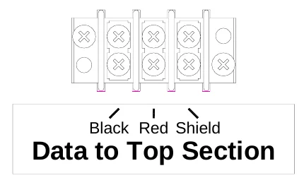
Control Cable Connections to Upper Scoreboard Cabinet The following steps describe how to connect data to the upper scoreboard cabinet: 1.There is a cable attached to the upper access panel terminal block labeled Data from Bottom Section. Feed the cable through one of the holes in the plate below the access panel. 2.Install the cable in conduit and feed the cable through one of the holes in the plate below the lower access panel. 3.Connect the cable to the terminal block labeled Data to Top Section according to figure 7.
4.
Reinstall the upper access panel.
Power Connection to Scoreboard The scoreboard requires 120 VAC service at the scoreboard to operate properly. Maximum power consumption of Model 1480: 228 Watts. Make sure that power cable is rated for this electrical load. Install the power cable in conduit. Avoid running the power cable in close proximity to the control cable. The following steps describe how to connect the scoreboard to the power source: 1.Feed the power cables through a hole in the plate below the lower access panel. 2.Crimp fork terminals to the power cable wires. 3.Connect the AC line wire and AC neutral wire to the Main Power terminal block on the junction chassis according to Figure 8.
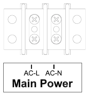
Install a power disconnect that isolates all current carrying conductors on one of the posts below the scoreboard (not the ground conductor). If a secondary switch is installed near the scorekeeper’s table, it should also isolate these conductors. Place the power disconnect in the OFF position between games to help protect the scoreboard from lightning damage. A power disconnect on the scoreboard post also provides a convenient way of turning the scoreboard off during maintenance or repairs.
ScoreLink 300 The ScoreLink 300 RF MODEM SYSTEM is designed to eliminate the control cable between the scoreboard and the control console on Electro-Mech Scoreboard MM and MP series scoreboards as well as all LED scoreboards. If you have purchased this accessory, disregard the section of this manual titled Control Cable Installation. Refer to the ScoreLink 300 RF MODEM SYSTEM OWNER’S HANDBOOK for installation instructions.
Control Cable Installation The control cable connects the scoreboard to the control console. Install the control cable in conduit. If the cable is ever damaged, it is easier and less expensive to replace a cable in conduit. A small junction box with a ¼” stereo jack mounted on the face plate is attached to the control cable at the point of operation of the scoreboard. This junction box should be securely mounted in a clean, dry area within ten feet of the rear of the control console. Most customers order the control cable with the junction box attached. Some customers prefer to attach the junction box after the cable is installed. Those customers must solder the control cable to the ¼” stereo jack. Figure 9 shows the control cable wire connection points on the rear of the ¼” stereo jack.
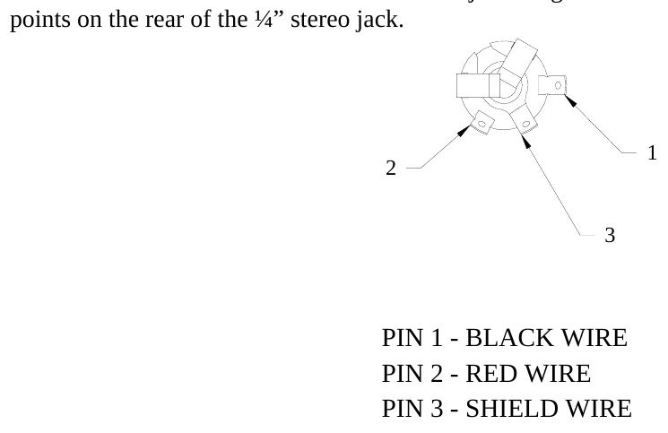
The following steps describe how to connect the control cable to the scoreboard: 1.At the rear of the scoreboard feed the control cable one of the holes in the plate below the lower access panel. 2.Crimp fork terminals to the control cable wires and the shield. 3.Connect the control cable to Control Cable terminal block on the lower access panel junction chassis according to figure 10.
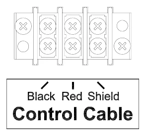
4.
Reinstall the lower access panel.
Control Console Connections The 10 ft. extension cable has two molded ¼” stereo plugs attached to it. It is used to connect the control console to the junction box. The following steps describe how to connect the control console:
1.
Plug one end of the extension cable into ¼” stereo jack on the junction box or the ScoreLink 300 Transmitter, if purchased. Plug the other end into the ¼” stereo jack mounted on the control console back plate. Plug the control console power cord into a grounded NEMA 5-15R 120 VAC receptacle.
2. 3.
Control Console Safety Warning
This product is equipped with a 3-wire grounding type plug, a plug having a third (grounding) pin. This plug will only fit into a grounding-type power outlet. This is a safety feature. If you are unable to insert the plug into the outlet, contact a qualified electrician to replace your obsolete outlet. Do not defeat the purpose of the grounding-type plug.
SCOREBOARD STARTUP
1. 2.
Place the power disconnect for the scoreboard in the ON position. Plug one end of the extension cable into ¼” stereo jack on the junction box or the ScoreLink 300 Transmitter, if purchased. Plug the other end into the ¼” stereo jack mounted on the control console back plate. Plug the control console power cord into a grounded NEMA 5-15R 120 VAC receptacle. If a ScoreLink 300 RF MODEM SYSTEM is installed with this scoreboard, plug the wall mount DC power supply into a grounded NEMA 5-15R 120 VAC receptacle and the male plug on the end of the attached cable into the Power jack on the Transmitter.
3. 4. 5.
GAME TIME OPERATION
This scoreboard is operated with a 37-key control console. Figure 11 shows the keypad layout on the control console.
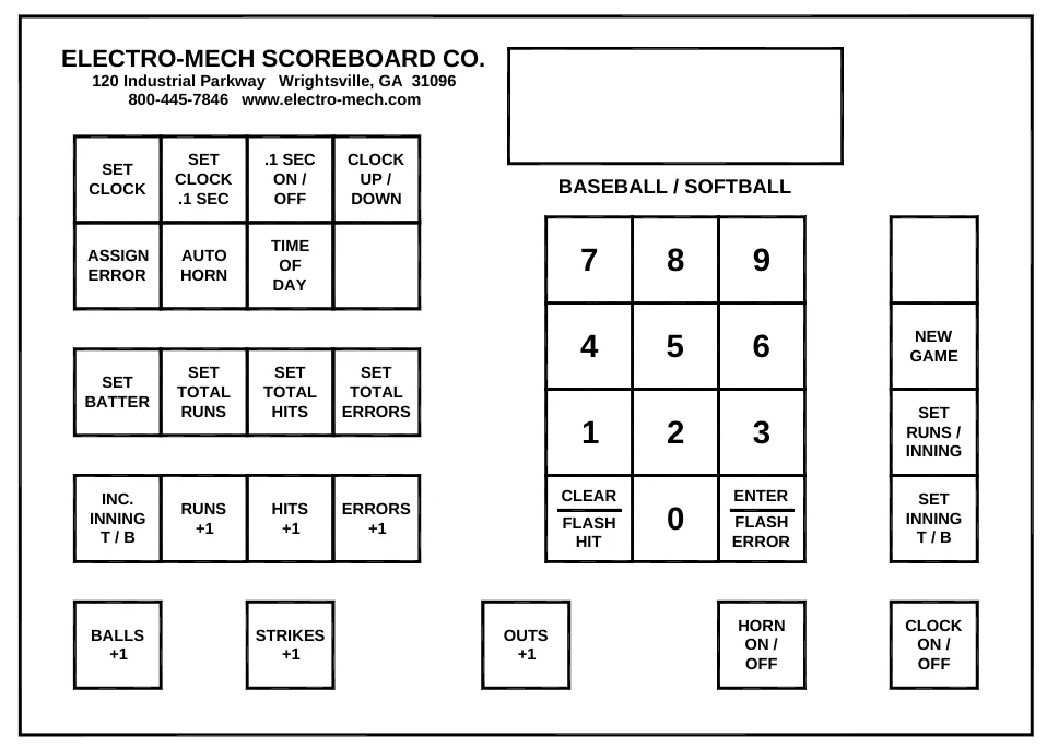
Immediately after the control console power cord is plugged into a 120 VAC source, the console LCD display will read:
ELECTRO-MECH 274 SCOREBOARD MPB14
After a few seconds the display will read:
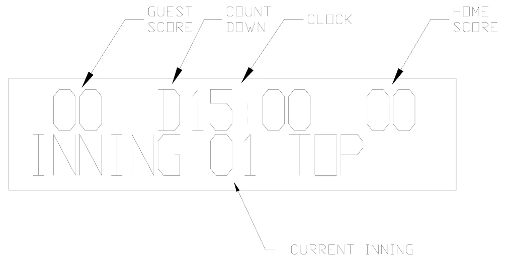
00 D15:00 INNING -
The scoreboard will display:
BATTER – 0 GUEST RUNS – 0 GUEST HITS – 0 GUEST ERR – 0 HOME RUNS – 0 HOME HITS – 0 HOME ERR – 0
The control console LCD display shows the total runs for the HOME and GUEST teams. It also provides instructions to help the operator use some of the console functions. Note: The total HITS, total ERRORS, BATTER number, BALLS, STRIKES, OUTS, HITS, and ERRORS will be displayed on the scoreboard, but not on the console. There is a clock function displayed on the control console, not on the scoreboard. Figure 12 explains the LCD display layout.
Control Console Key Functions
1.
INC INNING T / B – This key increments the inning to the next half inning. When the console is turned on, the LCD display will read:
00 D15:00 INNING -
Press [INC INNING T / B]. The LCD display will then read:
00 D15:00 00 INNING 01 TOP
The console is set to the top of the first inning. Pressing the key again increments the console to the bottom of the first inning. Note: The innings will increment from 1 to 19. For innings greater than 19, the INNING TEN digit will remain illuminated. The result is that innings 20 to 29 will be displayed on the scoreboard as innings 10 to 19.
2.
SET BATTER – Press [SET BATTER]. The LCD display will read:
00 <00>
Press [1][3][ENTER] to set the BATTER number to 13.
3.
SET TOTAL RUNS – Press [SET TOTAL RUNS]. The LCD display will read:
00 D15:00 00 TOT RUNS TOP<00>
Press [3][ENTER] to set the GUEST runs to 3. The LCD display will then read:
00 D15:00 00 TOT RUNS BOT<00>
Press [2][ENTER] to set the Home runs to 2.
4.
SET TOTAL HITS – Press [SET TOTAL HITS]. The LCD display will read:
00 D15:00 00 TOT HITS TOP<00>
Press [4][ENTER] to set the GUEST hits to 4. The LCD display will then read:
00 D15:00 00 TOT HITS BOT<00>
Press [5][ENTER] to set the Home runs to 5.
5.
SET TOTAL ERRORS – Press [SET TOTAL ERRORS]. The LCD display will read:
00 D15:00 00 TOT ERRS TOP<00>
Press [7][ENTER] to set the GUEST errors to 7. The LCD display will then read:
00 D15:00 00 TOT ERRS BOT<00>
| 00 D15:00 00 | ||||||
| TOT ERRS BOT<00> | ||||||
| Press [1][ENTER] to set the Home errors to 1. | ||||||
| 6. | RUNS +1 | – This key will increment the total runs by 1. | ||||
| 7. | HITS +1 | – This key will increment the total hits by 1. The Hit indicator (H) will flash four times. | ||||
| 8. | ERRORS +1 | – This key will increment the total errors by 1. The Error indicator (E) will flash four | ||||
| times. | ||||||
| 9. | BALLS +1 | – This key will increment the Balls by 1. | ||||
| 10. | STRIKES +1 | – This key will increment the Strikes by 1. | ||||
| 11. | OUTS +1 | – This key will increment the Outs by 1. | ||||
| 12. | SET INNING T / B | – This key is used to change the current inning. Press [SET INNING T / B] and | ||||
| the LCD display will read: | ||||||
| 00 D15:00 00 | ||||||
| SET TO INN <00> | ||||||
| Press [5], [ENTER] to change to the fifth inning. The LCD display will read: | ||||||
| 00 D15:00 00 | ||||||
| TOP=0/BOT=1 <00> | ||||||
| Press [1], [ENTER] to select the bottom of the inning. The LCD display will read: | ||||||
| 00 D15:00 00 | ||||||
| INNING 05 BOTTOM | ||||||
| 13. | CLEAR / FLASH HITS | – This key has two purposes. It can be used to clear incorrect keypad | ||||
| entries. It can also be used to flash the Hit indicator (H) on the scoreboard. | ||||||
| 14. | ENTER / FLASH ERRORS | – This key has two purposes. It is used when entering game | ||||
| information. It can also be used to flash the Error indicator (E) on the scoreboard. | ||||||
| 15. | NEW GAME | – This key is used to reset all the scoreboard functions to their default settings. To reset | ||||
| the scoreboard, press [NEW GAME] | . The console LCD display will read: | |||||
| RESET YES<1> | ||||||
| SCOREBOARD NO<0> | ||||||
| Press [1] | , [ENTER] | on the control console. The scoreboard will reset its functions. | ||||
| The SET CLOCK, SET CLOCK .1 SEC, .1 SEC ON / OFF, CLOCK UP / DOWN, ASSIGN ERROR, | ||||||
| AUTO HORN, TIME OF DAY, HORN ON / OFF, SET RUNS / INNINGS, CLOCK ON/OFF, and | ||||||
| DIMMER keys are not used with the 1480 scoreboard. | ||||||
| You should reset the scoreboard each time that it is turned on. Test out all the functions to ensure that the | ||||||
| scoreboard is operating properly. | ||||||
| Electro-Mech Scoreboard Co. | • 120 Industrial Parkway • Wrightsville, GA 31096 |
SCOREBOARD SHUTDOWN
1. 2. 3. 4.
Place the power disconnect for the scoreboard in the OFF position. Unplug the control console power cord. Unplug the extension cable. If a ScoreLink 300 RF MODEM SYSTEM is installed with this scoreboard, unplug the Transmitter’s wall mount power supply. Store the control console and ScoreLink 300 Transmitter in a dry location. These units are not waterproof.
5.
Proper scoreboard shutdown will help protect the scoreboard and control console from power surges and lightning strikes.
SERVICING THE SCOREBOARD
While your scoreboard was designed for years of trouble-free operation, some problems may occasionally occur. Electro-Mech Scoreboard Company offers onsite service in some areas. In other areas, we can help you contact an independent service technician. In areas in which service is not available from Electro- Mech Scoreboard Company, we will make every effort to answer your questions. Our trained personnel at Electro-Mech Scoreboard Company are ready to answer your questions from Monday to Friday during the hours of 8 AM to 5 PM Eastern Standard Time. Be sure to know your scoreboard model number when calling. Scoreboard replacement parts are always available. Damaged parts can usually be repaired at a significant cost savings. Our convenient toll free number is listed at the bottom of every page in this manual.
If the scoreboard turns on LEDs, but does not operate normally, make note of which functions are affected. If some LEDs either never turn on or always stay on, make note of their specific locations on the scoreboard. Refer to the COMPONENT REPLACEMENT section of this manual before changing parts.
COMPONENT REPLACEMENT
LED digits are serviced from the front of the scoreboard. All other components are located behind the rear access panels.
LED Digits And Indicators Replacement
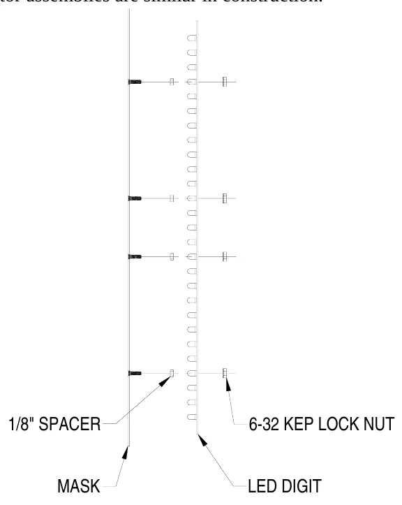
The LEDs that form digits and indicators are soldered on circuit boards mounted behind metal masks. Do not attempt to replace individual LEDs. In case of a malfunction, the entire LED circuit board must be removed. To avoid damage to the LED driver module,always turn off the power to the scoreboard when removing or replacing LED digits and indicators. Figure 13 shows the components of a LED digit assembly. LED indicator assemblies are similar in construction.
1.
Remove the sheet metal screws that fasten the mask to the face of the scoreboard. Caution: Support the mask before removing the last screw. The ribbon cable that connects to the rear of the circuit board is not designed to support the weight of the assembly.
2.
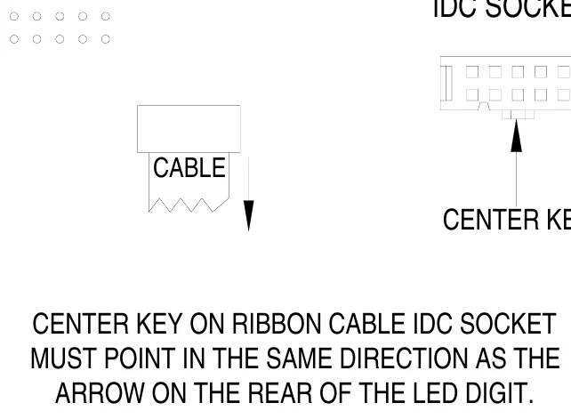
Disconnect the ribbon cable from the rear of the circuit board. Caution: Do not let the cable hang outside of the scoreboard. It is easily cut by sharp metal edges. Damage to the ribbon cable may create short circuit paths that will damage the LED driver module. Place the assembly on a flat surface and remove the 6-32 kep lock nuts that hold the circuit board in place. Remove the circuit board. Align the mounting holes in the circuit board with the threaded studs on the mask and install the replacement digit on the mask. Plug the ribbon cable onto the header on the back of the circuit board. Refer to figure 14 in order to plug the ribbon cable IDC connector onto the circuit board in the proper orientation.
3.
4. 5.
6.
RIBBON CABLE IDC SOCKET
7.
Reinstall the assembly using the sheet metal screws.
Single Segment Driver Board Replacement
1.
Remove the sheet metal screws that fasten the mask to the face of the scoreboard. Caution: Support the mask before removing the last screw. The wires and cables that connect to the rear of the LED digit and Single Segment Driver Board are not designed to support the weight of the assembly. Disconnect the ribbon cables from the rear of the LED digit and Single Segment Driver Board Caution: Do not let the cables hang outside of the scoreboard. Ribbon cables easily cut by sharp metal edges. Damage to a ribbon cable may create short circuit paths that will damage the LED driver module. Disconnect the wire assembly from the Single Segment Driver Board J3 jack. Place the assembly on a flat surface and remove the 6-32 kep lock nut that holds the Single Segment Driver in place. Remove the old circuit board. Install the replacement circuit board. Fasten the circuit board in place with the 6-32 kep lock nut.
2.
3. 4.
5. 6. 7.
All other components are located behind the rear access panels. Figure 15 shows the view behind the lower access panel.
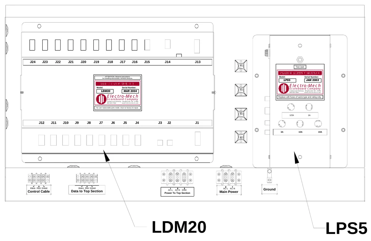
LDM20 LED DRIVER MODULE FUNCTIONS
| Figure 15 Lower Access Panel Components | ||||||
|---|---|---|---|---|---|---|
| LDM20 LED DRIVER MODULE FUNCTIONS | ||||||
| DRIVER MODULE | ||||||
| JACK | FUNCTION #1 FUNCTION #2 | |||||
| J1 | DRIVER MODULE DC POWER INPUT #1 | |||||
| J2 | SERIAL DATA INPUT | |||||
| J4 | HOME RUNS UNITS DIGIT | |||||
| J5 | HOME RUNS TENS DIGIT | |||||
| J6 | HOME HITS UNITS DIGIT | |||||
| J7 | GUEST RUNS UNITS DIGIT | |||||
| J8 | GUEST RUNS TENS DIGIT | |||||
| J9 | GUEST HITS UNITS DIGIT | |||||
| J13 | DRIVER MODULE DC POWER INPUT #2 | |||||
| J16 | INNING UNITS DIGIT | INNING TENS DIGIT | ||||
| J17 | HOME HITS TENS DIGIT | |||||
| J18 | HOME ERR DIGIT | |||||
| J20 | GUEST HITS TENS DIGIT | |||||
| J21 | GUEST ERR DIGIT | |||||
| Note: All other LDM20 jacks are unused. |
| LED Driver Modules Replacement | |||||||||||||
|---|---|---|---|---|---|---|---|---|---|---|---|---|---|
| Electrical connections to the LED DRIVER MODULES are made with ribbon cable polarized IDC sockets | |||||||||||||
| and locking ramp crimp terminal housings that mate with jacks on the module. The module is secured | |||||||||||||
| inside the scoreboard with four machine screws. | |||||||||||||
| 1. | Unplug the electrical connections from the module. Do not cut the plastic tie wraps around the ribbon | ||||||||||||
| cables. | |||||||||||||
| 2. | Remove the four screws. | ||||||||||||
| 3. | Remove the module from the scoreboard. | ||||||||||||
| 4. | Insert the replacement module in the scoreboard. | ||||||||||||
| 5. | Secure the module with the four screws. | ||||||||||||
| 6. | Insert the plugs into the jacks on the module. | ||||||||||||
| To avoid damage to the module, | always turn off the power to the scoreboard when removing or | ||||||||||||
| replacing it | . | ||||||||||||
| LPS5 LED POWER SUPPLY MODULE FUNCTIONS | |||||||||||||
| JACK FUNCTION | |||||||||||||
| J1 | 120 VAC INPUT | ||||||||||||
| J2 | 20 VDC OUTPUT TO LED DRIVER MODULE | ||||||||||||
| J3 | SERIAL DATA INPUT / OUTPUT | ||||||||||||
| J4 NOT | USED | ||||||||||||
| J5 | SERIAL DATA TEST JACK | ||||||||||||
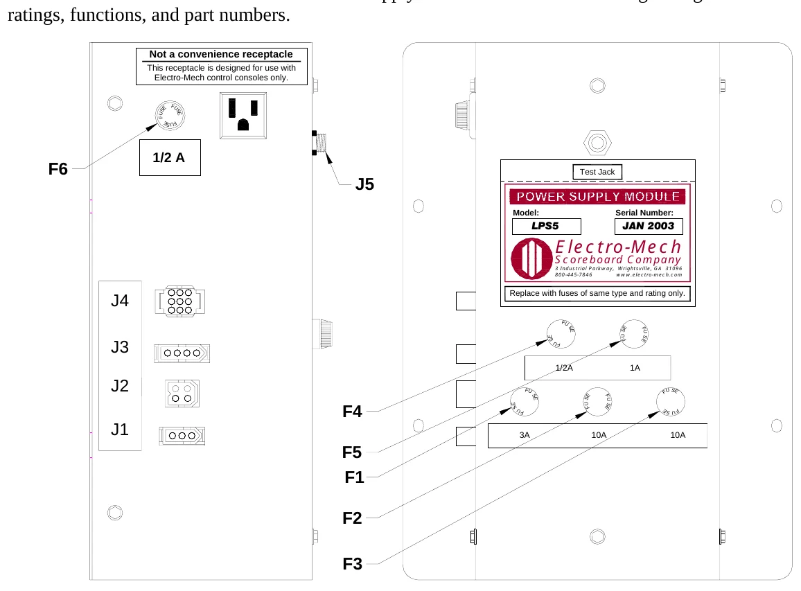
| A relay inside the LPS5 Power Supply Module isolates the LDM20 LED Driver Module from the control | |||||||||||||
| cable when the scoreboard is shut down. Connecting the control console to the test jack on the LPS5 | |||||||||||||
| Power Supply Module (J5) with the 10 ft. extension cable bypasses this relay. Figure 16 shows the | |||||||||||||
| location of the fuses in the LPS5 LED Power Supply Module. The table following the figure lists the fuse | |||||||||||||
| ratings, functions, and part numbers. | |||||||||||||
| Not a convenience receptacle | |||||||||||||
| This receptacle is designed for use with | |||||||||||||
| Electro-Mech control consoles only. | |||||||||||||
| S E F U ES | |||||||||||||
| U F | |||||||||||||
| 1/2 A | |||||||||||||
| F6 | |||||||||||||
| J5 | Test Jack | ||||||||||||
| Model: | Serial Number: | ||||||||||||
| LPS5 | JAN 2003 | ||||||||||||
| Electro-Mech | |||||||||||||
| Scoreboard Company | |||||||||||||
| 3 Industrial Parkway, Wrightsville, GA 31096 | |||||||||||||
| 800-445-7846 www.electro-mech.com | |||||||||||||
| J4 | Replace with fuses of same type and rating only. | ||||||||||||
| F U | S E | E | F | ||||||||||
| S | U S | ||||||||||||
| J3 | E S | U F | |||||||||||
| 1/2A 1A | |||||||||||||
| J2 | |||||||||||||
| F U ES | E | F U | F U S E | ||||||||||
| F4 | S U | S | |||||||||||
| E S | F | ||||||||||||
| J1 | |||||||||||||
| 3A 10A 10A | |||||||||||||
| F5 | |||||||||||||
| F1 | |||||||||||||
| F2 |
| LPS5 FUSES | |||||
|---|---|---|---|---|---|
| FUSE RATING | FUNCTION | BUSSMAN PART # | |||
| F1 | 3A 250V | TRANSFORMER PRIMARY | AGC-3 | ||
| F2 | 10A 250V DRIVER MODULE DC POWER INPUT #1 | AGC-10 | |||
| F3 | 10A 250V DRIVER MODULE DC POWER INPUT #2 | AGC-10 | |||
| F4 | ½A 250V | SERIAL DATA ISOLATION RELAY | AGC-1/2 | ||
| F5 1A | 250V | NOT USED | AGC-1 | ||
| F6 | ½A 250V | 120 VAC ELECTRICAL RECEPTACLE | AGC-1/2 | ||
| Note: Other manufacturers’ fuses may be substituted for the Bussmann fuses. |
LED Power Supply Modules Replacement Electrical connections to the LED POWER SUPPLY MODULE are made with keyed plugs that mate with jacks on the left side of the module. The module is secured inside the scoreboard with four machine screws.
1. 2. 3. 4. 5. 6.
Disconnect the plugs from the four jacks on the module. Remove the four screws. Remove the module from the scoreboard. Insert the replacement module in the scoreboard. Secure the module with the four screws. Insert the plugs into the jacks on the side of the module.
To avoid damage to the module,always turn off the power to the scoreboard when removing or replacing it.
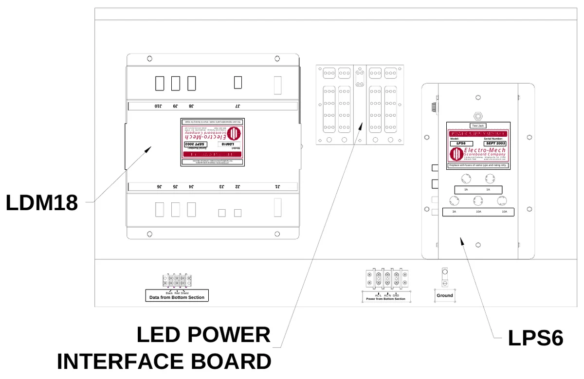
Figure 17 shows the view behind the upper access panel.
LDM18 LED DRIVER MODULE FUNCTIONS
| LDM18 LED DRIVER MODULE FUNCTIONS | ||||||
|---|---|---|---|---|---|---|
| From | DISPLAY #1 | DISPLAY #2 | ||||
| BATTER UNITS SINGLE SEGMENT | ||||||
| J4 | BATTER UNITS DIGIT (left header) | DRIVER BOARD J2 | ||||
| J5 | BATTER TENS DIGIT (left header) | |||||
| BALL DIGIT SINGLE SEGMENT | ||||||
| J6 | BALL DIGIT (left header) | DRIVER BOARD J2 | ||||
| J8 | OUT DIGIT (left header) | |||||
| J9 | STRIKE DIGIT (left header) | |||||
| BATTER UNITS SINGLE | ||||||
| SEGMENT DRIVER BOARD J1 | H indicator (seg h) | |||||
| BALL DIGIT SINGLE SEGMENT | ||||||
| DRIVER BOARD J1 | E indicator (seg h) | |||||
| Note: All other LDM18 jacks are unused. | ||||||
| LPS6 LED POWER SUPPLY MODULE FUNCTIONS |
LPS6 LED POWER SUPPLY MODULE FUNCTIONS
J1 J2 J3 J4 J5
JACK FUNCTION 120 VAC INPUT 20 VDC OUTPUTS SERIAL DATA INPUT / OUTPUT 12 VDC RELAY FUNCTIONS (NOT USED ON THIS SCOREBOARD) SERIAL DATA TEST JACK
Connecting the control console to LPS6 test jack (J5) with the 10 ft. extension cable enables the operation of the lower section of the scoreboard from the lower access panel. Disconnect the cable wires that are connected to the bottom of the terminal block labeled Data from Bottom Section. Figure 18 shows the location of the fuses in the LPS6 LED Power Supply Module. The table following the figure lists the fuse ratings, functions, and part numbers.
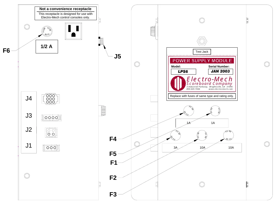
| Figure 18 LPS6 Fuse Locations | |||||
|---|---|---|---|---|---|
| LPS6 FUSES | |||||
| FUSE RATING | FUNCTION | BUSSMAN PART # | |||
| F1 | 3A 250V | TRANSFORMER PRIMARY | AGC-3 | ||
| F2 | 10A 250V | LED POWER INTERFACE BOARD J1 | AGC-10 | ||
| F3 | 10A 250V | LED POWER INTERFACE BOARD J6 | AGC-10 | ||
| F4 | 1A 250V | 12 VDC RELAY OUTPUT (NOT USED ON THIS SCOREBOARD) | AGC-1 | ||
| F5 | 1A 250V | 12 VDC RELAY OUTPUT (NOT USED ON THIS SCOREBOARD) | AGC-1 | ||
| F6 | ½A 250V | 120 VAC ELECTRICAL RECEPTACLE | AGC-1/2 | ||
| Note: Other manufacturers’ fuses may be substituted for the Bussmann fuses. |
The LED Power Interface board distributes the output from the LPS6 LED power supply module to the LDM18 LED driver module and some digits.
LED Power Interface Board Replacement 1.Unplug the wire assemblies from the jacks on the circuit board. 2.The circuit board is mounted on snap-in standoffs. Unseat the circuit board from the standoffs. 3.Press the replacement circuit board in place on the standoffs. 4.Plug the wire assemblies in the correct jacks on the circuit board. Each wire assembly is labeled to indicate the correct jack connection.
ELECTRO-MECH SCOREBOARD CO. FIVE YEAR LIMITED WARRANTY
THE ELECTRICAL COMPONENTS OF ALL ELECTRO-MECH SCOREBOARDS ARE GUARANTEED FOR A PERIOD OF FIVE (5) YEARS FROM THE DATE OF INVOICE AGAINST DEFECTS IN WORKMANSHIP OR MATERIAL AND WILL BE REPLACED OR REPAIRED WITHOUT COST TO THE OWNER PROVIDED THE EQUIPMENT OR PARTS ARE RETURNED POSTAGE-PAID TO THE FACTORY IN WRIGHTSVILLE, GA. SHIPPING BACK TO THE OWNER WILL BE VIA UPS GROUND SERVICE EXCEPT WHEN AIR OR SPECIAL METHOD OF RETURN IS SPECIFIED BY THE OWNER, IN WHICH CASE SHIPPING WILL BE FREIGHT COLLECT.
EXCLUDED FROM THIS WARRANTY ARE FUSES.
THIS WARRANTY DOES NOT INCLUDE LABOR CHARGES INCURRED IN THE REMOVAL OF COMPONENT PARTS, SERVICE CALLS, OR DAMAGES RESULTING FROM IMPROPER INSTALLATION, IMPROPER OPERATION, OR PROBLEMS CAUSED BY ANY REPAIR, ALTERATION OR MODIFICATION OF THE SCOREBOARD NOT PERFORMED BY ELECTRO-MECH.
EQUIPMENT WHICH IS SUBJECTED TO ACCIDENT, NEGLECT, ABUSE, MISUSE OR OTHER NATURAL DISASTERS, INCLUDING BUT NOT LIMITED TO FIRE, WIND, LIGHTNING, OR FLOOD, IS NOT COVERED BY THIS GUARANTEE.