
Home / Documentation / Control console manual
Download the original PDF (2153 kB)
This page reproduces the text of the PDF above without alteration, so the document can be read, searched and linked to directly.
- Type
- MULTISPORT
- Options
- 0C00
- Version
- CXvF / CX_402_v1.HEX
The above information should match the label on the bottom of your control console.
The purpose of this handbook is to explain how to use and maintain the Electro-Mech MP-Style control console for multi-sport scoreboard displays designed to show information for baseball, football, and other field sports. The explanations and examples are based on the CX-Series console driver hardware loaded with software version 4.0.2. Earlier versions of our hardware and software behave similarly, but not identically in all situations.
Scoreboard displays supported by this combination of hardware and software include these Electro-Mech models:
Seven Ways to Stay Safe and Make Your Console Last Longer
1 - Don't remove the grounding pin from the power cord. It's there to help keep you from getting shocked. If your AC power receptacle only handles two-pronged power cords then your wiring was probably installed sometime before President Hoover left office. It's time to upgrade.
2 - Keep your console dry. We've designed our consoles with outdoor activities in mind, but please find some shelter if it is raining. The box is not waterproof. Drinks spilled over the keypad can lead to trouble too.
3 - Unplug both the power and data cables when you are not using the console. Noise over these cables -- either from lightning, glitches in the power line, or some other accident -- can damage the console. Leaving the console connected 24-7 just increases your risk of getting it fried.
4 - Store the console in a clean, dry, secure area. Leave it where somebody can kick it, drop it, pile stuff on top of it, or steal it, and you can expect your console will get kicked, dropped, piled on, and stolen. See also the "keep your console dry" tip above. Neither sprinkler systems nor natural sources of precipitation are beneficial to your control console.
5 - If you must open the console box, unplug the power and data cables. Yes, it is possible to get shocked if you go poking around inside the console.
6 - Don't plug something into the console that doesn't belong there. Those stereo connectors in the back plate of the console are the same kind used by audio equipment. The RJ-45 connectors for the hand-held devices are the same type you often see in wired computer networks. Accidently plugging an audio amplifier or Ethernet access point into your scoreboard control console can cause problems -- both to your console and to your audio and networking equipment. A common mistake we see our customers make is to accidentally plug public address equipment into the junction box that leads to the scoreboard display. This can damage components in the scoreboard system.
7 - Check out your equipment before game day. We're always happy to answer questions, walk you through solutions, repair damage, or send replacement parts. But if your game starts in ten minutes, there may not be much we can do to help you. Make sure your scoreboard system is in good working order a few days before the game so that, however unlikely the chance of a problem, there will be time to solve it.
Console Parts and Accessories
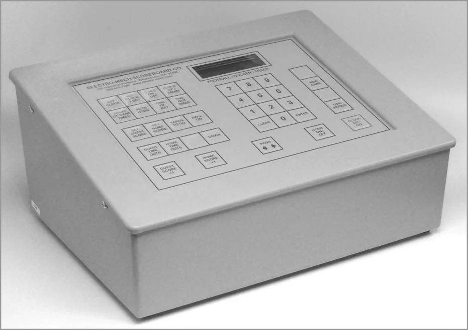
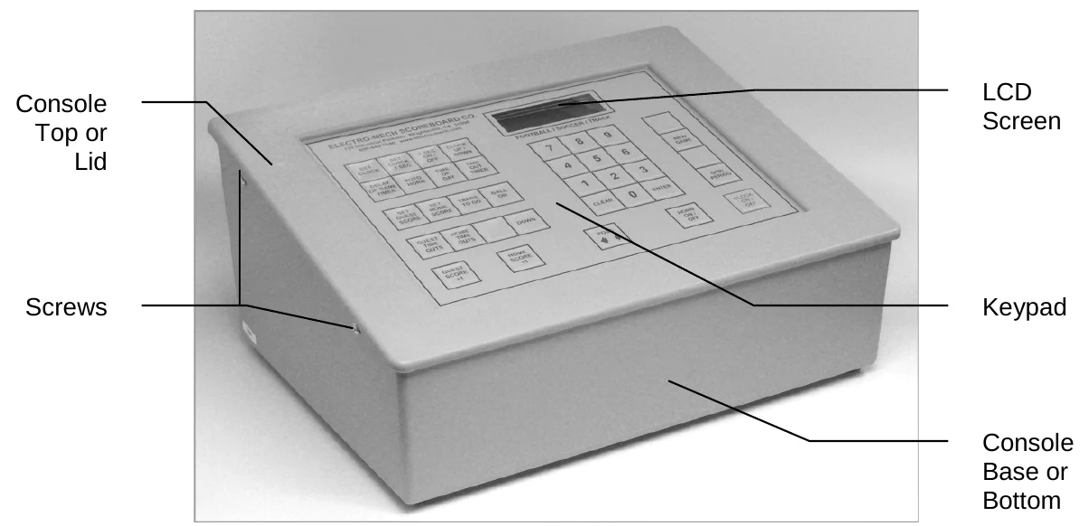
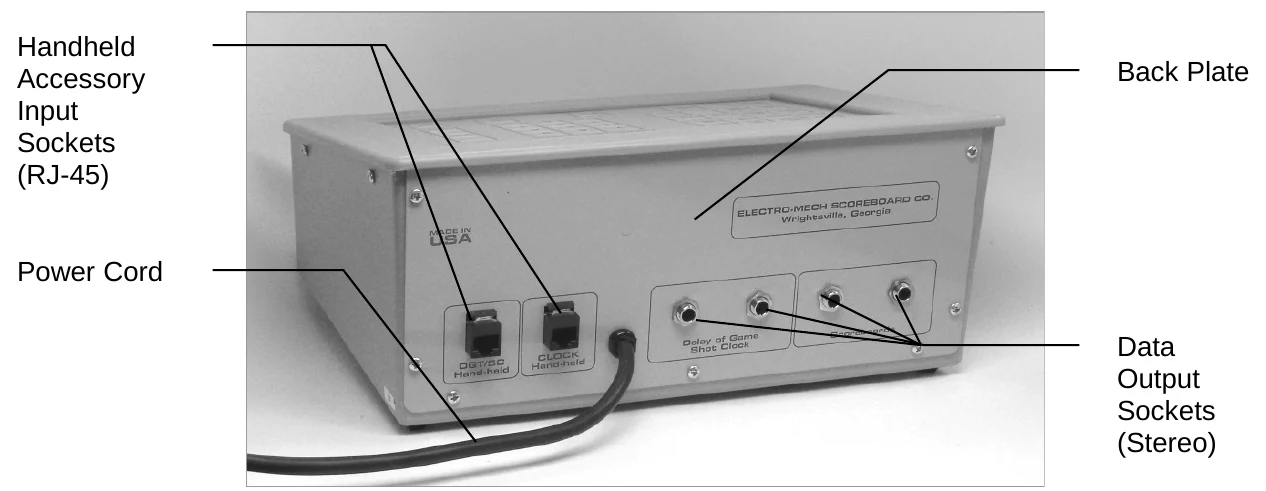
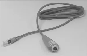
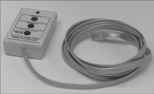
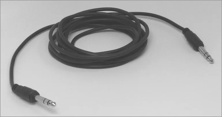
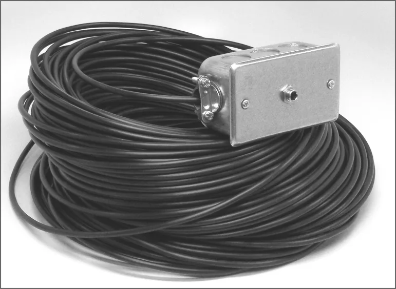
This is a generic set of photos identifying parts of the console and accessories. You should receive a packing slip or other paperwork with your order that tells specifically which parts you are supposed to have. Your configuration may be different.
Hooking Up and Powering Up the Console and Accessories
1 - Apply power to the scoreboard display(s).
2 - Place the console on a sturdy desk or table so that you have a clear view of the game's action as well as the console's keypad and LCD screen. You may hold the console in your lap, if you find it comfortable that way.
3 - Attach hand-held switch assemblies. You may have an external switch to start and stop the main Period Clock. This device plugs into one of the RJ-45 connectors on the console's back plate. It does not matter which RJ-45 socket you use.
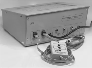
4 - Attach one end of the stereo data cable to one of the four data output connectors on the back plate of the console. Your console may have two outputs designated for the scoreboard display and two for Play Clocks or other optional displays. It doesn't really make a difference; all four outputs are the same. If you have multiple displays, go ahead and hook them up to whichever outputs are convenient.
5 - Attach the other end of the stereo data cable to the junction box. If you have more than one scoreboard or optional displays, each one will typically have its own junction box and its own stereo data cable. If you have the ScoreLink wireless RF system, refer to the ScoreLink owner's handbook for details.
6 - Plug the console power cable into a standard AC electrical outlet.
About one out of every few hundred customers asks us the question, "How do you turn the console on and off?" There is no power button on the console. If it's plugged in, it's on. The logic here is that, for most installations, the scoreboard is not used very often. During the down time, the console needs to be disconnected from the scoreboard display and from AC power to prevent damage from line noise and power surges. A power switch would discourage that good habit and provide a false sense of security.
Likewise, the scoreboard display should be disconnected from power when not in use. Therefore the console has no means of turning the sign on or off. However, a freshly powered on scoreboard display will show no information until it receives a good signal from the control console. So in order to completely "turn on" the scoreboard display, you have to power up and connect the control console.
Control Console Initialization
Be quick. You only have about three seconds to see the splash screen when your console powers up. It should look like this:
ELECTRO-MECH 402
MULTISPORT  0C00
The splash screen is telling you four things:
- The software author
- ELECTRO-MECH
- The software version
- 402
- The selected scoreboard type
- MULTISPORT
- The selected option jumpers
- C = 2- or 3-Digit Period Clock
This information is important for diagnostics, and you can get back to this splash screen by pressing [NEW GAME] [1] [ENTER] on the keypad. If you see something different on your LCD screen, either this is the wrong owner's handbook for you or your console is not configured to the expected standard.
If your console has data from the previous game, you will be prompted to restore that data. Press [1] [ENTER] to reload the old Scores and other information. Press [0] [ENTER] to clear out memory and start over fresh. If you do not respond to this prompt, the console will restore the previous game data automatically after a few seconds.
  RESTORE GAME?
1=YES  0=NO  <1>
After the splash screen clears, you will see the main game information screen:
00 D12:00  -  00
00  0-0-0 00
The scoreboard display will show the following information (some scoreboard models do not include all the functions listed):
- Left (Guest) Total Runs
- 0
- Home (Home) Total Runs
- 0
- Inning
- Blank (0 on some models)
- Ball
- Blank
- Strike
- Blank
- Out
- Blank
- Left (Guest) At Bat Indicator
- Blank
- Right (Home) At Bat Indicator
- Blank
- Left (Guest) Pitch Count
- 0
- Right (Home) Pitch Count
- 0
- Single Pitch Count
- 0
- Hit Indicator
- Blank
- Error Indicator
- Blank
- Period Clock
- 12 (minutes)
Control Console LCD Screen
The LCD screen primarily shows you the main game data screen. Information shown here corresponds closely (but not exactly) to information shown on the scoreboard display.
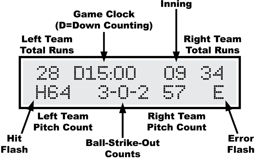
Numbers that display as "0" on the LCD screen may display as blanks on the sign. For instance, when the Strike Count reads "0" on the control console, the digit on the scoreboard display will be blank. Some scoreboard models do not include features like Pitch Count or Time, so, of course, the scoreboard display will not show all the information on the LCD screen in those cases.
The illustration above refers to "Left Team" and "Right Team" in order to be as generic as possible. In most cases, the Left side is for the Guest team and the Right side is for the Home team. Some scoreboard/console pairs ship with the positions swapped.
Key-By-Key Operation
This section will provide a key-by-key explanation of the console features. Use the [0] ... [9] buttons to respond to prompts, pressing [ENTER] to complete or confirm your response. The [CLEAR] button backs you out of a prompt without making changes.
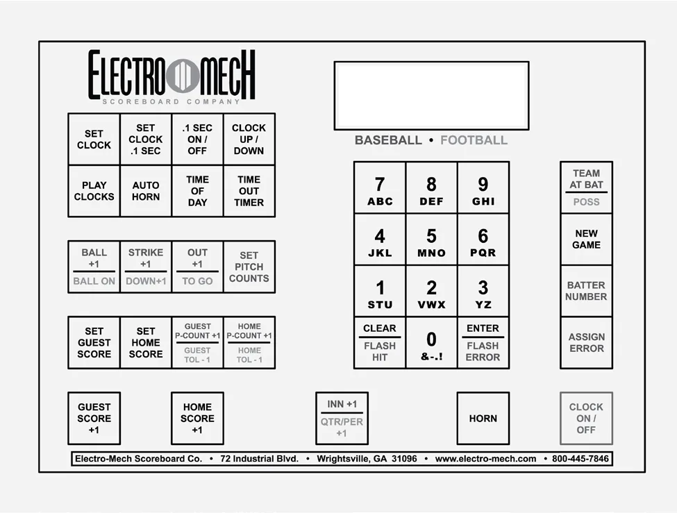
[SET CLOCK] - Available only when the Period Clock is NOT running. This button allows the operator to edit the time shown on the Period Clock. Pressing the button brings up an input prompt on the second line of the LCD screen.
SET CLK<0:12:00>
To set the time to 5:30, press [SET CLOCK] [5] [3] [0] [ENTER]. The console rejects time entries with a Seconds part greater than 59.
[SET CLOCK .1 SEC] - Available only when the Period Clock is NOT running and when it is in Down-Counting Mode with Tenth of Second Mode enabled. This button allows the operator to edit the time shown on the Period Clock during the final minute of the Period including the Tenth of Seconds digit. Pressing the button brings up an input prompt on the second line of the LCD screen.
SET SECS <00.0>
To set the time to 14.7 seconds, press [SET CLOCK .1 SEC] [1] [4] [7] [ENTER]. The console rejects entries greater than 59.9 Seconds.
[.1 SEC ON / OFF] - Available only when the Period Clock is NOT running and when it is in Down-Counting Mode. This button allows the operator to set the behavior of the Period Clock during the final minute of a Period. By default, during the final minute, the Period Clock shifts into Tenth of Second Mode, displaying Seconds in the area that usually shows Minutes, and Tenths of Seconds in the place where the Seconds Tens digit is otherwise seen. The operator may override this feature by disabling Tenth of Second Mode so that the Minutes and Seconds stay put and Tenths of Seconds are not displayed at all. Pressing the button brings up a two-line prompt on the LCD screen.
 1/10TH SECOND
1=YES  0=NO  <1>
To turn off Tenth of Second Mode, press [.1 SEC ON / OFF] [0] [ENTER]. To turn it back on, press [.1 SEC ON / OFF] [1] [ENTER] or reset the console with the New Game function.
[CLOCK UP / DOWN] - Available only when the Period Clock is NOT running. This button allows the operator to change the direction of the Period Clock. By default the Period Clock counts down until reaching 0:00. The operator may set the Period Clock to count up starting from any valid time. Pressing the button brings up a two- line prompt on the LCD screen.
COUNT UP OR DOWN
1=UP 0=DOWN  <0>
To count up, press [CLOCK UP / DOWN] [1] [ENTER]. The Period Clock on the LCD screen will show a "U" prefix to indicate Up-Counting Mode. A "D" is for Down- Counting Mode.
In Up-Counting mode, after 99:59, the Period Clock cycles to 0:00 and continues counting.
[PLAY CLOCKS] - Not used for this configuration of the control console.
[AUTO HORN] - Allows the operator to set the behavior of the Horn. By default, the Main Horn attached to the scoreboard display is activated for about four seconds at the end of each Period. That is, when the Period Clock counts down to 0:00, the Horn sounds. You can turn off this feature by using the [AUTO HORN] button. Pressing it brings up this prompt:
AT END OF PERIOD
1=AUTO 0=OFF <1>
To turn off the Automatic Horn at the End of Period, press [0] [ENTER] at this prompt.
[TIME OF DAY] - Not used for this configuration of the control console.
[TIME OUT TIMER] - Not used for this configuration of the control console.
[BALL + 1] - Increments the Ball Count by one.
[STRIKE + 1] - Increments the Strike Count by one.
[OUT + 1] - Increments the Out Count by one.
[SET PITCH COUNTS] - Allows the operator to directly set or edit the Pitch Counts for both Teams. At the first prompt you may change the Pitch Count for the Team displayed on the Left side of the scoreboard/LCD (usually the Guest Team).
PITCH CNT L<000>
At the second prompt you may change the Pitch Count for the Team displayed on the Right side (usually the Home Team).
PITCH CNT R<000>
The Team At Bat function is tied to the Pitch Count function for scoreboard displays that include only one set of Pitch Count digits. For these scoreboards, Pitch Count is shown only for the Team NOT currently At Bat. So the [TEAM AT BAT] button toggles between the two Pitch Counts.
[SET GUEST SCORE] - Allows the operator to directly set or edit the Guest Score. Pressing the button brings up an input prompt on the second line of the LCD screen.
SET SCORE <00>
To set the Guest Score to 35, press [SET GUEST SCORE] [3] [5] [ENTER].
Some scoreboard/console pairs ship with the positions of the Guest and Home keys swapped.
[SET HOME SCORE] - Allows the operator to directly set or edit the Home Score. Pressing the button brings up an input prompt on the second line of the LCD screen.
SET SCORE <00>
To set the Home Score to 42, press [SET HOME SCORE] [4] [2] [ENTER].
Some scoreboard/console pairs ship with the positions of the Guest and Home keys swapped.
[GUEST PITCHES +1] - Increments the Guest Pitch Count by one.
[HOME PITCHES +1] - Increments the Home Pitch Count by one.
[GUEST SCORE +1] - Increments the Guest Score by one.
[HOME SCORE +1] - Increments the Home Score by one.
[INNING +1] - Increments the Inning display by one.
[HORN] - Sounds the Horn for a two-second burst.
[CLOCK ON / OFF] - Starts and stops the Period Clock.
[CLEAR / FLASH HIT] - Flashes the Hit Indicator four times. This button is also used exit certain prompts without changing data.
[ENTER / FLASH ERROR] - Flashes the Error Indicator four times. This button is also used to confirm the entry of numerical data.
[ASSIGN ERROR] - Indicates the Position of the Fielder who commits an Error. Pressing the button brings up a prompt on the second line of the LCD:
ERR POSITION <0>
Press [ASSIGN ERROR] [2] [ENTER] to indicate an Error committed by the person in Position 2. This causes a few things to happen. On the sign, the "E" character (or other Error bullet) will flash four times. If your scoreboard display has an Error Fielder Number digit, it will flash (in this case, the number "2") along with the Error indicator.
Here's a quick reference for the numbers associated with Fielder Positions: 1 = Pitcher 2 = Catcher 3 = First Base 4 = Second Base 5 = Third Base 6 = Short Stop 7 = Left Field 8 = Center Field 9 = Right Field
[SET BATTER] - Allows the operator to set or edit the Player Number of person at bat. Pressing the button brings up an input prompt on the second line of the LCD screen.
BATTER NUM <00>
To set the Batter Number to 35, press [SET BATTER] [3] [5] [ENTER].
[TEAM AT BAT] - This button toggles the Team At Bat Indicator from the Left (usually Guest) Team to the Right (usually Home) Team and back. You can see the results of pressing this button as a little arrow that appears on the left or right side of the LCD display on the control console. Most scoreboard displays do NOT have a corresponding indicator.
The Team At Bat function is tied to the Pitch Count function for scoreboard displays that include only one set of Pitch Count digits. For these scoreboards, Pitch Count is shown only for the Team NOT currently At Bat. So the [TEAM AT BAT] button toggles between the two Pitch Counts.
"New Game" Features -- Including Electronic Team Name Setup
[NEW GAME] - Available only when the Period Clock is NOT running. This button is the doorway to one fairly obvious feature and a few other hidden features. Pressing it brings up the following display:
RESET SCOREBOARD
1=YES  0=NO  <0>
Press [1] [ENTER] to reset all game specific data to default values. For instance, Guest and Home Scores will be reset to 0.
In addition to this memory-clearing function, [NEW GAME] allows the operator to access other functions by entering other numbers at the prompt. These are listed below.
[NEW GAME] [2] - This sub-function controls the brightness (or dimming) of the scoreboard displays. You may set the brightness level to any value from 50% to 100% -- with 100% being the brightest.
 SET BRIGHTNESS
MAX=100%  <100%>
When you initially apply power to your scoreboard display, the LED digits and indicators will always reset to 100% brightness. The scoreboard display only receives a command to change brightness when you press [NEW GAME] [2] and enter a brightness value. So, if your sign loses and regains power during a game, it reverts to 100% brightness until you walk through this function again.
The brightness feature works on Electro-Mech LX-series scoreboards manufactured in 2012 or later. Older scoreboard models ignore the brightness command (and may flicker briefly in response).
[NEW GAME] [4] - This sub-function turns off all the digits and other indicators on the scoreboard display and shows the following message on the LCD screen:
***BLANK TEST***
**NEWGAME=EXIT**
Blank Test Mode is a diagnostic feature that allows you to check for LED circuits that are damaged in a way that prevents them from being turned off. If anything remains lit on the sign when the console is in this mode, there is a hardware problem that should be resolved by contacting technical support. The Decimal Indicators (if present) on Clocks may remain lit in some cases.
Exit this mode by pressing [NEW GAME] again.
This is also a handy trick for blanking the scoreboard display between consecutive games or whenever it is convenient. Just remember that the sign is not truly off in this state. The electronic components are still energized.
[NEW GAME] [5] - This sub-function turns on all the digits and other indicators on the scoreboard display and shows the following message on the LCD screen:
***LAMP TEST****
**NEWGAME=EXIT**
Lamp Test Mode is a diagnostic feature that allows you to check for LED circuits that are damaged in a way that prevents them from being turned on. If anything is blank on the sign when the console is in this mode, there is a hardware problem that should be resolved by contacting technical support. Two exceptions: Horns are not supposed to sound in Lamp Test mode, although Visual Horn Indicators should light up, and the Colon/Decimal Indicators (if present) on some Clocks will not light up in this mode.
Exit this mode by pressing [NEW GAME] again.
[NEW GAME] [7] - This sub-function controls Electronic Team Names. If your scoreboard display does not have Electronic Team Names (or if your scoreboard with ETNs was manufactured before 2011), the data and commands generated by this console feature will be ignored.
SET TEAM NAMES?
1=YES  0=NO  <1>
The ETN prompts refers to the Team displayed on the left side of the scoreboard display as Team 1; the Team on the right is Team 2.
Team 1
Setting the name is much like using the text features of a phone that assigns text characters to the number keys. Each time you press a number key repeatedly, the next character associated with that key appears on the LCD display. For instance, to enter the name "BEARS" you would press... [7] [7] = B [8] [8] = E [7] = A [6] [6] [6] = R [1] = S If you make a mistake entering a character, press the [CLEAR] key to back up one space. To complete the text entry, press [ENTER].
The next prompt allows you to choose the font:
SELECT FONT
  1-9        <3>
As of this writing, there are three available fonts: 1=Condensed, 2=Regular, 3=Bold.
The number of letters your ETN can show depends on the font you choose as well as the size of your sign.
After choosing a font style, you must select a justification:
SELECT JUSTIFY
1-L 2-C 3-R  <2>
Choose 1 for Left justification -- that is, the first letter in the Team Name will be flush with the left side of the ETN. Choose 2 for Center justification -- that is, the Team Name will be centered within the ETN. Choose 3 for Right justification -- that is, the last letter of the Team Name will be flush with the right side of the ETN.
The process is the same for Team 2. Note that font and justification settings for the two teams are independent of each other.
When your scoreboard with ETNs ships from Electro-Mech, the default Team Names are GUEST and HOME. Once you update the scoreboard display with new Team Names, those names become the default that you will see when the sign is powered up. The console will only update the ETN displays when you work through the [NEW GAME] [7] function while the console is connected to the sign. Because the text entry routine is designed to send characters to the scoreboard display as you enter them in the console, it is not possible to program the Team Names "in advance" and update the sign later.
Because of the occasional need to run a countdown time or other information on the Period Clock before the start of a game, you may be forced to program ETNs while the Period Clock is running. Since the [NEW GAME] button is disabled when the Period Clock runs, there is a "trick" to this. You must stop the Clock for the few seconds it takes to press [NEW GAME] [7]. Then you may start the Clock again. The Period Clock will continue to run while you update the ETNs.
The [NEW GAME] [4] Blank Test Mode will blank the ETNs (along with the rest of the sign). If you disconnect the console while the ETNs are blank, reset the console, and then reconnect it to the sign, the ETNs will remain blank. This is because the ETNs are only refreshed once, while the numeric scoreboard data is refreshed multiple times per second. You may restore blanked ETNs when the console is connected by entering and exiting "Lamp Test" Mode or "Blank Test" Mode or by resetting the console.
[NEW GAME] [8] - This sub-function configures the console to work with timing equipment provided by Precision Time Systems, Inc. You may confirm entry into this mode by typing [1] [ENTER] in response to this prompt:
PRECISION TIME?
1=YES  0=NO  <0>
The practical results of being in Precision Time Mode are 1) the [CLOCK ON / OFF] button is disabled, and 2) the Period Clock only runs when the console hardware reads a switch closure from an external clock switch. You can simulate the behavior of the Precision Time equipment by plugging an Electro-Mech Wired Hand-Held Clock Start/Stop Switch Assembly into one of the RJ-45 connectors on the back of the console and holding down the button on the handheld device to start the Clock. The Clock on the LCD screen will have a "P" prefix to indicate Precision Time Mode. To exit Precision Time Mode, press [NEW GAME] [8] [0] [ENTER].
Summary of [NEW GAME] functions
[0] = Exit [1] = Reset Game Data [2] = Brightness [3] = Not Used [4] = Blank Test [5] = Lamp Test [6] = Not Used [7] = Electronic Team Names [8] = Precision Time Mode [9] = Not Used Long Press = Maintenance Sub-Menu
[0] = Exit [1] = ScoreLink Signal Strength (not currently supported) [2] = AC Supply Voltage (partially supported) [3] = Not Used [4] = Radar Gun (not supported for this configuration) [5] = Not Used [6] = Not Used [7] = Not Used [8] = Not Used [9] = Not Used
Wired Handheld Clock Start / Stop Switch Assembly
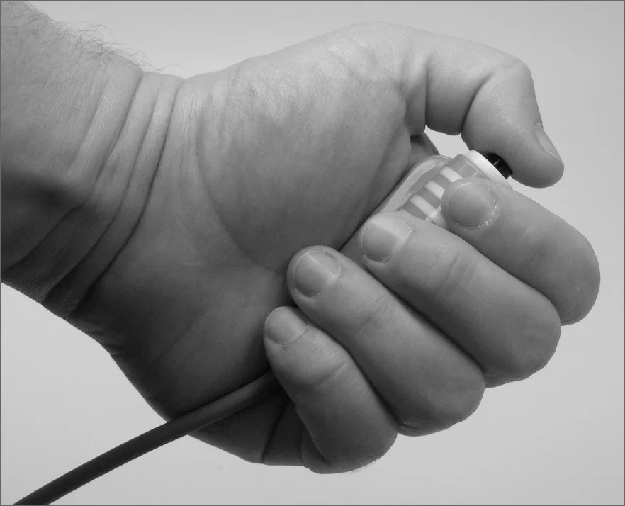
Some of our multi-sport scoreboard packages ship with a handheld pendant-style switch that plugs into the back of the control console and provides a separate operator the ability to start and stop the Period Clock. The RJ-45 style connector at one end of the handheld unit's cable can plug into either the console sockets labeled "H1" or "H2" in the "SWITCH INPUTS" area. On older control consoles, these sockets are labeled "CLOCK Hand-held" and "DGT / SC Hand-held". No matter what the labels imply, either RJ-45 socket should work the same as the other. The pendant end fits nicely in your hand so that your thumb rests on the switch. Press the switch once to start the Clock. Press the switch again to stop the Clock.
Control Console Power Down and Storage
There is no "OFF" switch on the control console; nor is there a function on the console that turns the scoreboard display off. The scoreboard display should be disconnected from power when not in use. Electro-Mech recommends installing a disconnect switch for all permanently mounted scoreboards. You may simply unplug a portable scoreboard display and store it between games.
You should unplug your control console both from its power receptacle and from its data cable when you are not using it. Electro-Mech offers a carrying case that provides a convenient way to store and transport the console along with various cables and other accessories. Whether or not you have a case, you should store the console in a safe, dry location between games.
If the console loses its connection with the scoreboard display while the sign is powered, the display will freeze up -- showing the last known Time, Score, and other information it received from the console. The scoreboard display will synchronize with the console again as soon as you reestablish the connection.
If the scoreboard display loses power while the console is still connected and powered, nothing will happen other than the sign going blank. Again, the scoreboard display will synchronize with the console as soon as power is restored at the sign.
If the console loses power -- either because you intentionally unplug it or because of something unexpected -- it will save the current game information to its internal memory. When you next apply power to the console, the LCD will prompt you to restore the previous game. If you fail to respond to the prompt, the game data will restore automatically after a few seconds.
Jumper Settings
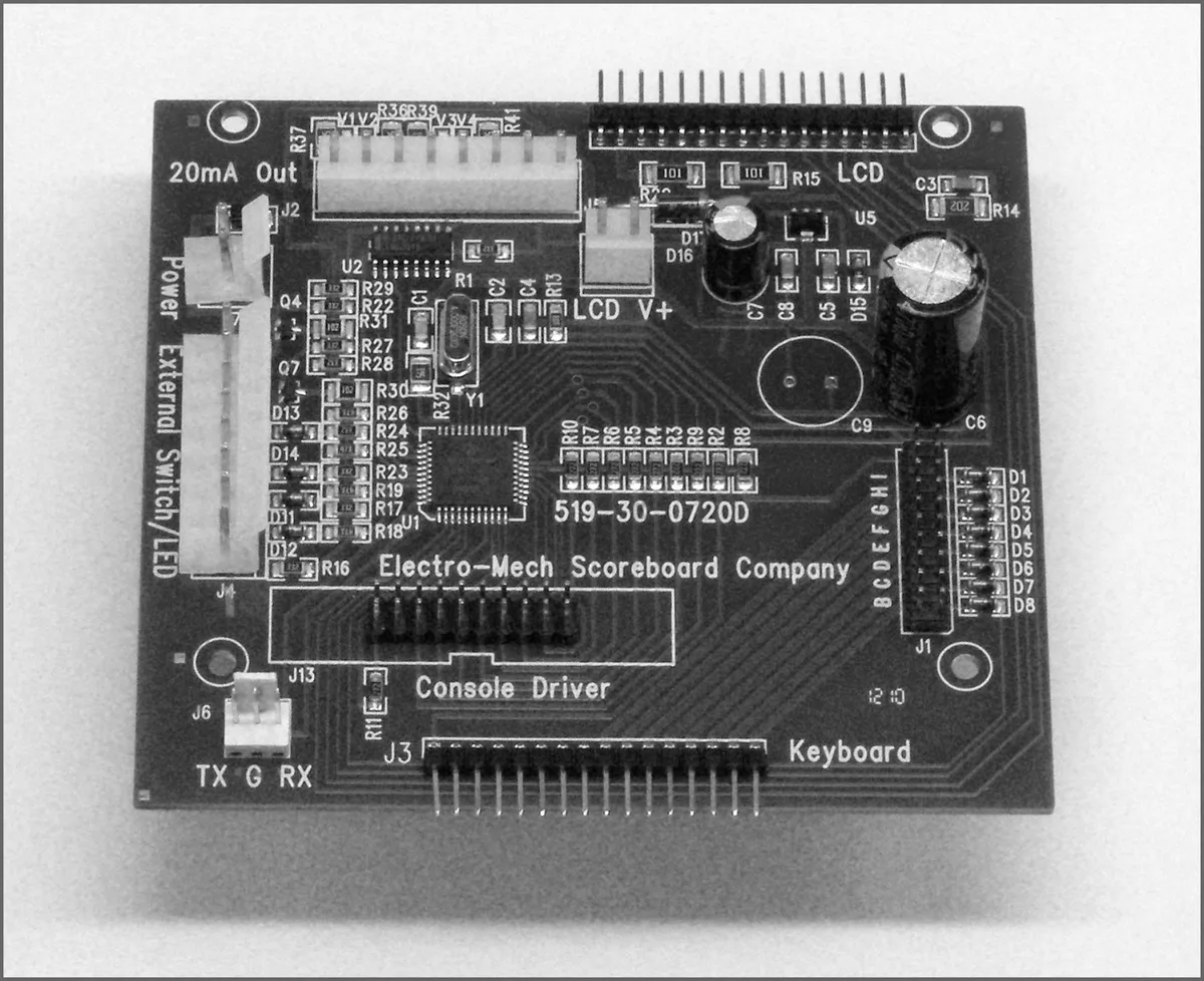
*** Important: If you plan to open up the console and do work inside the box, make sure the power cable is disconnected from the receptacle! ***
The PCB that is the heart of the CX console is called the CX driver. This driver contains a set of jumper pins that can be used to tell the software how to behave. By installing shunts across a pair of pins, you are, in essence, closing a switch that tells the program to do something. On some CX drivers these pins are labeled B through I, A through I, or A through J. On other drivers the A, B, C,... labels are missing, but you will find a corresponding diode next to pins B through I (A and J are not for jumpers). The diodes are labeled D8 through D1 (D8 = B, D7 = C, etc.).
Jumper pins A and J are used for attaching a programming cable to the CX driver and don't really do anything in this context. Pins F, G, H, and I are the "Board Type Jumpers" that determine the sport. So, for instance, by removing the shunt across the G pins, you can make your console think it is operating a typical Electro-Mech football scoreboard rather than a multi-sport scoreboard. This table summarizes the jumper settings for the Board Type Jumpers:
| Board Type | F | G | H | I | Models / Comments |
|---|---|---|---|---|---|
| BASEBALL_3 | LX10xx, LX12xx, LX134x | ||||
| BASEBALL_4 | X | LX1360 | |||
| FOOTBALL_4 | X | LX1360, LX31xx | |||
| BASEBALL_1 | X | X | LX10xx, 11xx, 12xx, 134x | ||
| BASEBALL_2 | X | Not used | |||
| SOCCER_LX | X | X | Not a part of CX_402 Software | ||
| SOCCER | X | X | Not a part of CX_402 Software | ||
| HOCKEY | X | X | X | Not a part of CX_402 Software | |
| LINESCORE4 | X | Not used | |||
| LINESCORE5 | X | X | LX16xx, LX17xx | ||
| FOOTBALL_1 | X | X | LX3xxx, LX7520, LX7640 | ||
| BASKETBALL | X | X | X | LX2xxx (except Player Stats), LX72xx | |
| MP-14X | X | X | Not used | ||
| MP-15X | X | X | X | Not used | |
| MULTISPORT | X | X | X | LX13xx, LX3450, LX6324 | |
| HOCKEY_LX | X | X | X | X | Not a part of CX_402 Software |
Pins B, C, D, and E are the "Option Jumpers". Each one typically controls one of four options for a given Board Type. This document discusses the options for the Multi- Sport Board Type only. You'll have to look at the Owner's Handbooks for consoles configured for the other Board Types if you are curious about their Option Jumpers.
Jumper B = LX3450 Mode (Add this jumper to operate LX3450). Jumper C = 2D/3D Clock (Remove this to indicate MM:SS Period Clock). Jumper D = Not Used. Jumper E = B-S-O to 4-3-3 (Install this jumper for Balls to 4, Strikes & Outs to 3).