
Home / Documentation / Owner's manual
Download the original PDF (1863 kB)
This page reproduces the text of the PDF above without alteration, so the document can be read, searched and linked to directly.
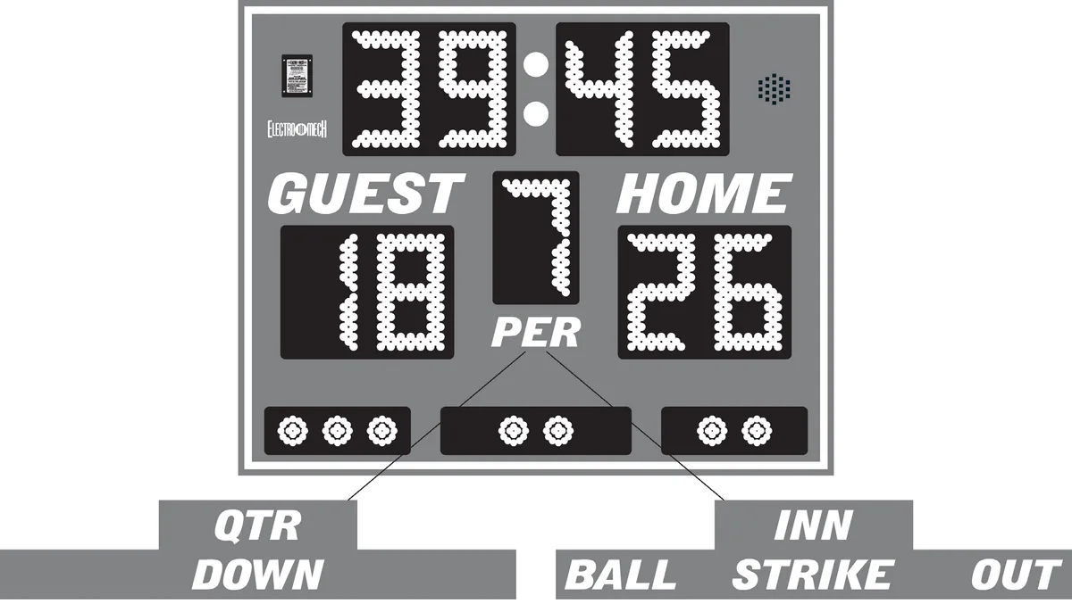
The purpose of this manual is to explain how to install and maintain the Electro-Mech Model LX1320 Outdoor Multi-Sport scoreboard. Operation of the scoreboard is covered in the manual that ships with the control console.
Model LX1320 is designed primarily for portable use, although it can be permanently installed. This scoreboard display is compatible with Electro-Mech's T-Cart leg kit. Documentation that ships with the leg kit includes assembly instructions.
BEST PRACTICES FOR PERSONAL SAFETY AND PRODUCT CARE
Thank you for choosing Electro-Mech products for your athletic facility. We hope you will be pleased with the performance and appearance of your scoreboard. The information in this document will help you maintain the equipment in its best condition.
Receiving Your Scoreboard
Depending on the shipping method, cardboard sheets, a partially open wooden crate, or a complete enclosure may protect the scoreboard cabinet. It is important to inspect the scoreboard packaging for damage when it arrives ─ before signing any paperwork telling the trucking company that you have received everything in good condition. If damage has occurred to the packaging, then damage may have occurred to the scoreboard. Where you find dents, scrapes, or holes in the packaging, peel back the cardboard or other packing materials to expose the scoreboard cabinet. Make notes on the paperwork provided by the trucking company before accepting delivery. If the damage appears to be severe, refuse the shipment. Contact Electro-Mech as soon as possible if you suspect shipping damage.
We recommend keeping the scoreboard display in its packing materials until the day of installation. It is important to keep the packing materials dry while they are on the scoreboard. Wet cardboard can adhere to the scoreboard face and damage the finish.
If your scoreboard cabinet arrives in a wooden crate, take care to avoid scraping the cabinet with tools, nails, or lumber when prying apart the nailed sections. Make certain to pry the wooden pieces apart from each other rather than trying to apply force against the scoreboard cabinet. Aluminum is strong, but a steel crowbar is stronger.
Once the crate is out of the way, remove the cardboard padding. You may need to remove a few labels adhered to the side of the cabinet for shipping. At this point, your scoreboard cabinet is unpacked and ready for installation.
Storage Prior to Installation
Unless you are planning to install your scoreboard on the same day it arrives, you will need to prepare a clean, dry, secure area for storage. Even though your scoreboard display is designed for outdoor use, you will need to keep it away from rain, dirt, accidental damage, and abuse. As an example of why this is important, outdoor scoreboard cabinets include drain holes along the bottom. These drain holes will likely become clogged with dirt if the sign is stored on the ground, especially in the rain.
Stand the scoreboard cabinet upright prior to assembly; never lay it facing up or down. Never stack things on top of the scoreboard cabinet while it is in storage.
These recommendations apply equally to ID panels and other items that may have shipped with your scoreboard.
Conditions of Installation and Use for Outdoor Scoreboards
This scoreboard display is designed for installation and use in a wet environment. That is, rain and other common weather conditions will not hinder the operation of this product when it is installed correctly. The scoreboard cabinet is not watertight. Instead, it is designed to withstand normal outdoor conditions by routing water through the cabinet and out of drain holes in the bottom. Do not block the drain holes. If the scoreboard display is to be installed immediately above something ─ for instance, an ID panel or the ledge of a wall ─ please allow 1/4-inch or more clearance below the cabinet. Alternatively, you could provide matching drain holes in the top of the object below the scoreboard.
Although this scoreboard display was designed for portable use, it may be installed permanently. Outdoor scoreboard displays are typically installed on steel posts. It is important to properly install these posts and allow concrete footings time to cure before using them to support the scoreboard cabinet.
The scoreboard display includes an AC power cord fitted for a standard 120 VAC electrical outlet. When the display is not in use, you should disconnect it from power. For portable models, this typically means unplugging the power cord. In situations where access to the power cord will be difficult, we recommend installing a disconnect switch near the scoreboard display. In the "off" position, the switch should isolate all load-carrying conductors (not the ground). Disconnecting power will help protect the scoreboard electronics from nearby lightning strikes and other power fluctuations that might otherwise travel along the power cables.
PRODUCT SPECIFICATIONS
General Description:
- Model LX1320 is an electronic scoreboard designed for temporary, portable use or permanent installation outdoors. The purpose of Model LX1320 is to display time and scoring information for baseball and softball, or football and soccer.
Standard Package Includes:
- One scoreboard cabinet
- Four 1/2-inch-13 X 2-inch long bolts for mounting
- Detachable power cable with GFCI feature
- One control console
- One wired Period Clock Start/Stop switch
- One stereo patch cable
- One junction box (when configured to use hardwired data cable)
Cabinet Dimensions and Weight:
- 5 ft (W) x 4 ft (H) x 4 in (D), 50 lb
Cabinet Construction and Finish:
- The cabinet is formed from sheet aluminum. The face and back sections are also made from aluminum sheet material, as are the masks protecting the illuminated digits and other lighted elements. Mask and face pieces are finished with enamel paint. Captions, optional accent striping, and other decorative elements are cut from exterior grade vinyl. Electro-Mech offers eighteen standard paint and vinyl colors. Other color options are available as an upgrade.
Overview of LED Display Circuit Boards:
- Red or amber LEDs (light emitting diodes) mounted on PCBs (printed circuit boards) form all lighted digits and indicator elements. The color choice is determined at the time of purchase. All illuminated PCBs include conformal coating for weather protection. These circuit boards are mounted behind aluminum masks, painted black to increase contrast. The masks allow the epoxy shells of the LEDs to protrude past the scoreboard face, maximizing viewing angle while providing impact-absorbing protection from contact with stray balls and other flying objects. The LEDs may be dimmed to reduce glare during night games. They are rated for 100,000 hours of use.
Display Features:
- 4-Digit Period Clock, 11 inches tall, shows Time in MM:SS up to 99:59, counts up or down, can show Tenths of Seconds during the final minute of a down-counting Period, can show HH:MM in Time of Day Mode, can show a Segment Clock in Practice Segment Timer Mode
- 2-Digit Scores (one set for Guest, one set for Home), 11 inches tall, to 99.
- 1-Digit Period/Inning/Quarter, 11 inches tall, to 9
- 3-Bullet Ball Count Indicators, 3-inch diameter
- 2-Bullet Strike/Down Count Indicators, 3-inch diameter
- 2-Bullet Out Count Indicators, 3-inch diameter
Additional Standard Scoreboard Features:
- All serviceable components accessible from the front of the cabinet
- Internally mounted Horn
- Slim cabinet size for portability
- Integrated side mounting points for use with Electro-Mech's T-Cart leg kit
Control Console:
- The console includes custom software running on an internal microprocessor, a 32-character LCD display, a 37-button sealed membrane keypad, and a 6-ft. power cord. The console enclosure consists of an ABS plastic base and top with a metal back plate.
- Four data output ports can each directly drive a scoreboard display through a single cable run and indirectly drive up to ten displays in perfect synchronization via daisy chaining. The number of synchronized displays is practically limitless when using the optional ScoreLink RF communications system.
- The software includes support for Practice Segment Timer Mode, Time of Day Clock Mode, 50 levels of brightness, and other features.
Optional Equipment and Features:
- T-Cart leg kit for portable use
- Data cable for hard-wired installations
- ScoreLink RF communications system for wireless data transmission
- Hard carrying case for control console and accessories
Power Requirements:
- The LX1320 scoreboard display requires one circuit providing 0.9 amps, 120 VAC, 60 Hz.
- Power enters the display through a detachable power cord designed to plug into a standard (NEMA 5-15R) power receptacle. The power cord should be unplugged when the display is not in use.
- The control console requires one circuit providing 0.5 amps, 120 VAC, 60 Hz via a standard (NEMA 5-15R) power receptacle.
Mounting Requirements:
- The display is designed to be supported on each side. Support is typically provided by the two leg pieces of Electro-Mech's optional T-Cart leg kit. However, the cabinet may be bolted to a variety of permanent or portable structures.
- The cabinet will fit between two posts or brackets spaced 60 inches apart.
- Support posts or brackets may be attached to the cabinet using a pair of 1/2-inch-13 bolts on each side.
- To receive these bolts, the hardware inside the cabinet is tapped with holes vertically spaced 9 inches center-to-center.
Safety Listing, Support, and Warranty Information:
- All LX-series scoreboard displays are ETL Listed to UL Standard 48 for Electric Signs.
- Electro-Mech offers technical support at no charge over the phone or via the Internet for the life of the product.
- The standard limited warranty covers factory labor on parts returned to Electro- Mech within five years of the scoreboard's date of invoice.
- Additional support plans are available.
- The complete standard warranty statement is included near the end of this document.
PLANNING YOUR SCOREBOARD INSTALLATION
A good plan is important to the success of any project, and installing a scoreboard is no exception. An important first step in planning for your scoreboard is determining its optimal location. Key factors here are visibility and accessibility.
By "accessibility" we mean the ease with which you can get people, equipment, cabling, etc. to a scoreboard display during installation, as well as ease-of-access for future service. Positioning the display on a tall, steep embankment or backed up against a densely wooded area can add cost to installations as well as to service calls. When this display is equipped with the optional wheeled leg kit, accessibility is not much of a concern. But it is possible to mount the sign permanently, in which case, such factors should be kept in mind.
By "visibility" we mean the ease with which spectators, participants, and the scoreboard operator can see the display. Because every playing field is unique, there is no one-size-fits-all way to describe the perfect scoreboard location. But we can tell you that, in the United States, your best bet is to put the scoreboard display on the South or West side of the field (facing North or East). This will reduce glare from the setting sun during afternoon games. For other locations, the more general version of this advice: Avoid facing the sun.
Choosing a Direction

For portable systems, the planning is more likely to be focused on running power to the location(s) you need. For permanently installed displays, it is important to remember that the athletes, who are likely to be tall, will want to see the clocks over the heads of their teammates, opponents, or anyone else on the field.
Unless you've selected a very small scoreboard for a very large field, viewing distance is not usually an issue. The rule of thumb in the sign industry is that, for lighted characters, every inch of height provides 50 feet of viewing distance. For comfort, and because you also need to read the captions on a scoreboard, we prefer to recommend 25 feet of viewing distance per inch of digit height. Model LX1320 uses 11-inch tall digits, meaning it can easily be seen from 275 feet. If your players and spectators need to be several hundred feet or more from the scoreboard, your field may require a larger display.
When mounting this sign permanently, the height of the scoreboard display above the ground is important for several reasons. For safety, you don't want to position any sign where people are likely to smack their heads into it. Also, when they are easily within reach, the power and other cables running into the cabinets can prove tempting to
bothersome hands. For these reasons, as well as visibility above players on the field, you should usually keep the bottom display at least eight feet above ground level. While there is theoretically no upper limit on the height, you must consider stability of your structure and serviceability. In other words, the taller the sign, the larger the posts and footings will need to be. And, the taller the sign, the more difficult it will be to service.
The optional T-Cart Leg Kit, offered as an upgrade for this scoreboard, raises the bottom of the cabinet approximately 31 inches above the ground. If you use an alternative portable mounting system to provide more height, we recommend caution in evaluating the stability of the structure. There are no clear-cut guidelines for designing a support that is perfect for all occasions, but is import to keep in mind that the face or back of a scoreboard cabinet provides a lot of surface area for the wind to push against.
Other factors, such as the availability of power or the nature of the terrain (too rocky or too swampy), can play a role in determining scoreboard display location. When in doubt, feel free to discuss options with your scoreboard sales rep.
The sections that follow in this document discuss the details of mechanical and electrical installation of a scoreboard display. If your project includes multiple scoreboards or other electronic displays, please check with your scoreboard sales rep to make sure you have any project-level documentation you may need.
Before You Spend Your Time and Money...
Please keep in mind that the dimensions and other details referenced throughout this document are specific to the standard configurations of this particular scoreboard model. Before purchasing materials, digging holes, etc. you should verify with the factory that you have the right documentation for your unique project.
It is possible that a government agency, such as your local city council, will require a building permit or other documentation and approval forms related to the installation and operation of your scoreboard display. In some cases, particularly in coastal regions where hurricanes are a concern, the installation plan may require a stamp from a locally licensed Professional Engineer (P.E.).
MECHANICAL INSTALLATION
This section of the manual describes installing the scoreboard display, in its standard configuration. This scoreboard was designed for portable use. You may provide a permanent structure if you like. However, in most cases, these displays will be mounted on a portable stand. Electro-Mech offers a "T-Cart" portable leg kit for this purpose. Instructions for attaching the portable leg kit are provided in the documentation that ships with that product.
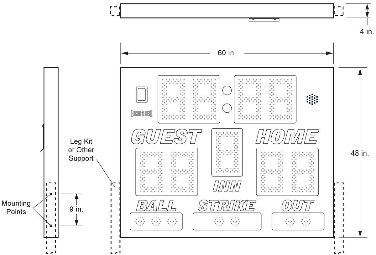
If you wish to attach your scoreboard display to a different support structure, you may take advantage of the mounting plates included on each side of the cabinet. These plates have tapped holes, spaced nine inches center-to-center. The tapped holes accept 1/2-inch-13 threaded bolts. Although the options for support structures are almost limitless, a pair of 3-inch wide square tubes, one bolted to each side of the cabinet, makes a good example of post supports for a permanent installation. For Model LX1320, support brackets or posts will need to be positioned 60 inches apart (inside spacing) to provide room for the cabinet.
ELECTRICAL INSTALLATION
The standard configuration of this scoreboard system includes a detachable power cord with GFCI protection feature. We recommend testing the GFCI feature during the initial installation and subsequently at intervals of three months or less. The GFCI test procedure is imprinted on the body of the AC plug housing.
Power and data cables enter the cabinet via an opening in the back. Sockets for power and data are protected by a cover plate. The cover plate is held to the back of the scoreboard cabinet by two thumb screws. You will find an extra captive nut in the back of the cabinet, which is there so that you can rotate the cover plate up and hold it out of your way temporarily while you plug in the cables.
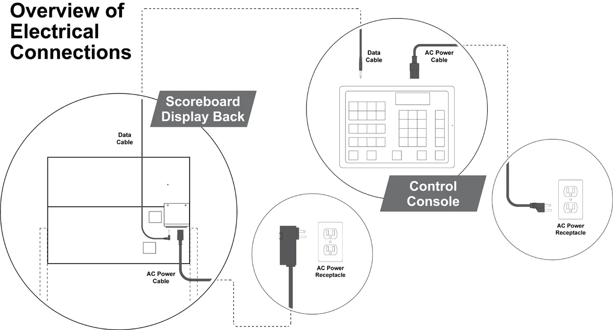
If your facility requires another method for attaching power or data cables ─ for instance, if you need to mount this display on a wall ─ we can provide other options for routing and terminating the electrical connections. Let your scoreboard sales rep know about any special requirements BEFORE we begin building your cabinet. If your scoreboard package includes special accessories such as a Stadium Sound System or Video Display, there may be additional cabling and conduit needed to support this equipment. Please consult the documentation provided with these items.
Power Considerations
A portable scoreboard display requires a standard (NEMA 5-15R) AC power receptacle providing 120 VAC at 60 Hz. On the other side of the AC receptacle, the power may come from an inverter attached to a battery charged by solar energy, a gasoline powered generator, or the local power company. It is beyond the scope of this document to consider all the possible variations. Here we will assume that the receptacle is available. Likewise, we will assume another receptacle is available for the control console.
Model LX1320 Outdoor Multi-Sport display draws a maximum of 0.9 amps. Use only the detachable power cord with the GFCI safety feature to connect the display to a power receptacle. If this cord is lost or becomes damaged, contact Electro-Mech to purchase a replacement. We do not recommend operating this display – especially outdoors –without a cord that includes the GFCI feature.
The control console also ships with a detachable AC power cord. Because the console is not designed for use in a wet environment, its power cord does not include the GFCI feature. The control console will draw a maximum of 0.5 amps.
TESTING, OPERATION, AND ONGOING CARE
As mentioned in the previous section, we recommend testing the GFCI safety feature on the scoreboard display's AC power cord during the initial installation process. Afterwards, assuming the cord is in good condition, apply power to the scoreboard display first. Although there is no harm in powering the control console first, the illuminated digits and indicators on the sign will remain blank if the scoreboard display receives power before it receives data. Any LEDs that are illuminated on the sign in this condition would indicate a problem at the scoreboard display.
Next, power up the control console and, for wired setups, use a stereo patch cable to connect one of the console's data output ports to the data input port at the display. The scoreboard should begin showing data within a few seconds. Make sure buttons on the control console produce responses at the scoreboard display. You may need to consult the documentation that ships with the control console to test certain features.
For scoreboards with Clock features, set the Clock to count down the final 30 seconds of a Period. If your scoreboard includes a Horn, it will (by default) sound when the Clock reaches 0.
Scheduled Testing and Maintenance
Aside from regular testing of the GFCI portion of the AC power cord, the scoreboard system does not require scheduled maintenance procedures. However, it is important to check for problems prior to a game, practice, or other usage. We recommend running through the tests described above between two and four weeks prior to the start of a season (or anytime you plan to use the scoreboard after a gap of more than a month). During the season, test out the scoreboard the day before each game or practice session.
After the Game, and After the Season
Whenever you are not using your scoreboard system, unplug the power and data cables and store them. You should unplug the control console from its power source and from the data cable as well. While portable outdoor scoreboard displays are designed to survive under most weather conditions, we recommend moving the sign to a protected area when it will not be used for more than a few days. This precaution is aimed primarily at discouraging people from bothering the unattended sign.
MAINTENANCE
We hope your scoreboard system provides years of trouble free service. In the event of a problem, the material that follows will provide some information about contacting technical support as well as some details about the parts inside your scoreboard display.
Contacting Technical Support
Our support staff is available via phone or e-mail Monday through Friday 8:00 through 5:00 Eastern. Our web address and phone number is printed at the bottom of this page. When contacting Electro-Mech for support, it helps to have the scoreboard model (LX1320) handy as well as the version of the software running on your control console. If your control console includes an LCD display, you will see the software version flash briefly (for about three seconds) on the screen when you first apply power. Whether you have the LCD display or not, you should find on the bottom of the control console a product label which gives the software version.
If you are reading this manual in search of help with a different scoreboard model, for outdoor scoreboards, you can find the model number printed on a metal plate attached to the back of the scoreboard cabinet near where the power enters. For indoor scoreboards, the model number is usually printed on a label at the top center of the cabinet near the attachment point for the power cable.
If you are troubleshooting a problem, the most important information to have is an exact description of which parts of your scoreboard system are working and which parts are not working. The best person to make contact with our support team is someone who has seen the problem first hand. Better yet, give us a call when you are there at the scoreboard display and can walk through a few simple tests with one of our technicians.
Scoreboard problems are rarely so complicated that diagnosing them requires skills beyond using a screwdriver and a ladder. Similarly, replacing parts is straightforward process that does not require complex tools or special knowledge.
Parts Exchange
If, after working with our support staff, you discover that a part needs to be serviced or replaced, the next step is to send the part to Electro-Mech for repair. During the warranty period, we repair parts and return them via UPS ground service at no charge. We can ship parts via overnight service for an additional charge. For work that falls outside of the warranty terms, we can, upon request, provide an estimate of repair costs on returned parts before performing the work. The typical turnaround on repair work is less than three business days
Electro-Mech maintains a supply of common parts for immediate shipment. Some customers choose to purchase new parts for immediate use and will later send old parts back to us to be repaired and returned as "backup" stock. In some cases our support plans include the option for shipping replacement parts to the customer once our service staff has identified a problem. The customer will then return the damaged part after receiving the replacement. Electro-Mech requires a valid credit card number before initiating a shipment of this type. We do not apply charges to the card unless the customer does not return parts within ten days or if the returned parts require work outside of our warranty terms.
Our shipping address:
Electro-Mech Scoreboard Co. 72 Industrial Blvd. Wrightsville, GA 31096
Location of Serviceable Parts
All serviceable parts are located behind the Score LED digit assembly on the right side of the scoreboard cabinet. This is typically the Home Score position. The next section of this document discusses removing and replacing LED digit assemblies.
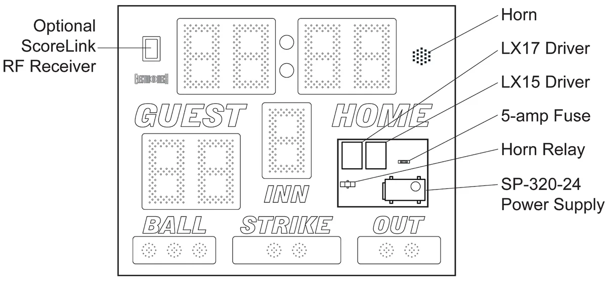
If your scoreboard system includes a ScoreLink wireless data kit, the receiver unit will be located in the upper left corner of the display face. The internal Horn will be mounted in the upper right corner. To access the Horn for service, remove the Period Clock Seconds digit assembly.
Illuminated PCB Assemblies
The LED assemblies and circuit boards (but not individual LEDs) are field replaceable parts. Each LED is soldered to a printed circuit board (PCB) which is, in turn, attached to a protective metal mask. The mask assembly is attached to the scoreboard face with machine screws. You will need a 1/4-inch nut driver to remove these screws.
Removing an LED Assembly, Step-By-Step:
- Disconnect power to the play clock cabinet before performing any service work.
- Remove the machine screws from the metal mask, leaving for last one of the screws along the top of the mask.
- Support the mask with one hand as you remove the final screw.
- Rotate the mask so that you can see the PCB (or PCBs) behind it and the cable connections along the back side.
- Unplug the ribbon cables, and, if present, the power cables from the PCBs.
- Set the LED assembly aside and save the screws for later.
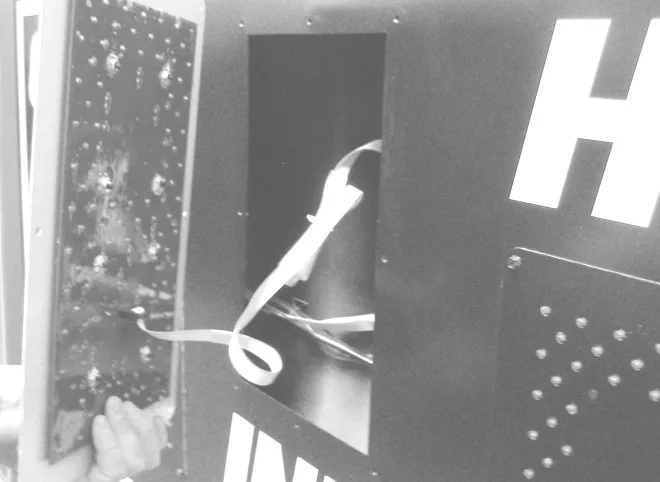
If your purpose in removing the LED assembly was to provide access to the components behind it, you may skip the next part about removing and replacing the LED printed circuit board.
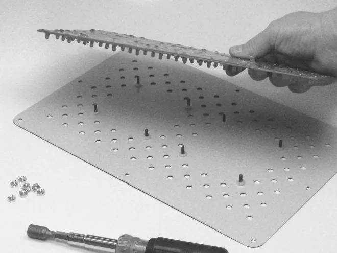
The LED circuit board is held to the mask by several nuts, which you can remove using a 3/8-inch nut driver. On outdoor displays the thick conformal coating can be messy, as the lock washers on the nuts dig into the coating and knock pieces of it away. Be careful to keep the whole assembly right side up when you return it to the play clock cabinet.
Power Supply and Fuse
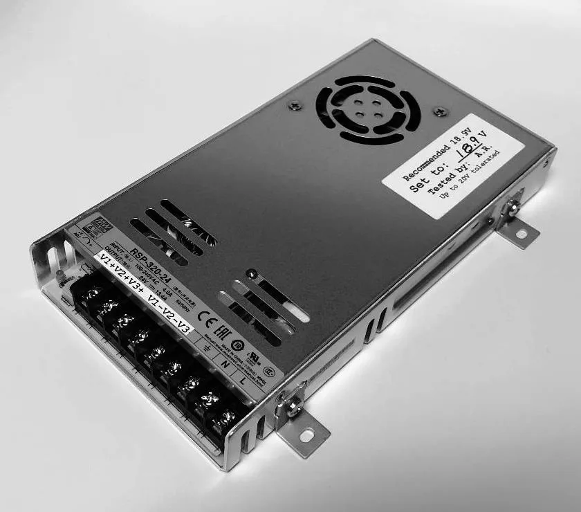
The AC power socket on the cabinet back is the point of entry for power at the scoreboard display. From this socket, the line side of AC passes through a 5-amp fuse on the way to the Mean Well RSP-320-24 power supply module. The fuse is AG style and should only be replaced with a fuse of the same style and rating.
Power connections are made along a row of screw terminals on one side of the power supply module. The Mean Well RSP-320-24 module provides 18.9 VDC to the illuminated digits and indicators along with the driver. If you replace a power supply module, check the output voltage to make certain it is set to 18.9 VDC.
LX Drivers
The LX Driver circuit boards do the work of interpreting data sent from the control console to the scoreboard display. Using that information, the drivers decide which of the LEDs should be illuminated and which should not. Each LX Driver in this system decodes data representing a specific set of digits or other indicators used in the scoreboard. The drivers send signals to the LED circuit boards via ribbon cables.
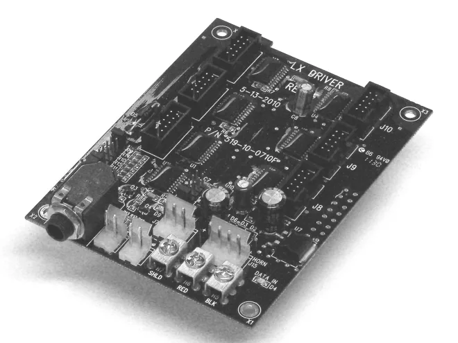
Data flows from one LX driver to the next in order, starting at the lower chassis (if there is more than one), and then left to right within each chassis. In the table(s) below, columns identify the LX Drivers, listed in order, left to right, based on the data path. The table rows give the names and purposes of the various connectors on the LX Drivers.
| Connector | LX17 | LX15 |
| J2 (Data In) | From ScoreLink | |
| J3 (Data Out) | To LX15 | To Data Out Terminal Block |
| J4 (Word 1 Low) | Period Clock Minutes Ones | Right (Home) Score Ones |
| J5 (Word 1 High) | Period Clock Minutes Tens | Right (Home) Score Tens |
| J6 (Word 2 Low) | Period Clock Seconds Ones | Left (Guest) Score Ones |
| J7 (DC Power In) | 18.9 VDC | 18.9 VCD |
| J8 (Word 3) | Q uarters | |
| J9 (Word 2 High) | Period Clock Seconds Tens | Left (Guest) Score Tens |
| J10 (Word 4) | ||
| J15 | Horn Relay | |
| H5/BLK (Data In) | From cable | From LX17 |
| H6/RED (Data In) | From cable | From LX17 |
| H7 /SHLD (Data In) | From cable | From LX17 |
| Jumper Pins | LX17 | LX15 |
| H13 (J4/J5 Blanking) | ||
| H16 (J4/J5 Blanking) | X | X |
| H14 (J6/J9 Blanking) | X | |
| H17 (J6/J9 Blanking) | ||
| H15 (Not Used) | ||
| H18 (Test Prog) | ||
| H3 (Horn2 No Dim) | X | X |
| H11 (Horn1 No Dim) | X | X |
| H19 (Not Used) | ||
| H1 (Memory Ret.) | ||
| H2 (Group +1) | X | |
| H4 (Bank +2) | X | |
| H12 (Bank +1) | X |
LIMITED WARRANTY STATEMENT
Electro-Mech Scoreboard Company Standard Equipment Warranty and Limitation of Liability for Scoreboards and Accessories Sold in the United States
Warranty Coverage
Electro-Mech warrants to the original end-user that the Equipment will be free from Defects (as defined below) in materials and workmanship for a period of five years from the date of invoice. Electro-Mech's obligation under this warranty is limited to, at Electro-Mech's option, replacing or repairing any Equipment or Part thereof that is found by Electro-Mech not to conform to the Equipment’s specifications. Any defective Part must be returned to Electro-Mech for repair or replacement. Equipment determined not to conform to specifications will be repaired or replaced and returned to purchaser with standard ground service transportation charges prepaid. Replacement Parts or Equipment will be new or serviceably used, comparable in function and performance to the original Parts or Equipment, and warranted for the remainder of the warranty period. Purchasing additional Parts or Equipment from Electro-Mech does not extend this warranty period.
Defects shall be defined as follows. With regard to the Equipment (excepting LEDs), a "Defect" refers to a material variance from the design specifications that prohibits the Equipment from operating for its intended use. With respect to LEDs, "Defects" are defined as LEDs that cease to emit light. The limited warranty provided by Electro- Mech does not impose any duty or liability upon Electro-Mech for partial LED degradation.
This limited warranty is not transferable.
Exclusions from Warranty Coverage
The limited warranty provided by Electro-Mech does not impose any liability upon Electro-Mech for:
- Damage caused by the unauthorized adjustment, repair, or service of the Equipment by anyone other than personnel of Electro-Mech or its authorized repair agents.
- Rental fees or other costs associated with lifts, cranes, or other tools and services used to access the Equipment.
- Damage caused by the failure to provide a continuously suitable environment, including, but not limited to (i) neglect or misuse (ii) a failure or surges of electrical power (iii) any cause other than ordinary use.
- Damage caused by vandalism, fire, flood, earthquake, water, wind, lightning, or other natural disaster, or by any other event beyond Electro-Mech’s reasonable control.
- Costs associated with replacement of communication methods including but not limited to, wireless systems, copper wire, fiber optic cable, conduit, or trenching for the purpose of overcoming local site interference.
- Any statements regarding products or services made by salesmen, dealers, distributors, or agents, unless such statements are in a written document signed by an officer of Electro-Mech.
Limitation of Liability
In no event shall Electro-Mech be liable for any special, consequential, incidental, or exemplary damages arising out of or in any way connected with the Equipment or otherwise, including but not limited to damages for lost profits, cost of substitute or replacement equipment, down time, lost data, or injury to property, or any damages or sums paid by the purchaser to third parties.